Product image is representative; revision or series may vary. Contact us to request a specific version.
1766-L32BWA
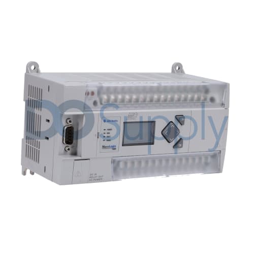
The 1766-L32BWA model serves as a programmable automation controller within the Allen Bradley MicroLogix 1400 series. This unit accommodates a total of 24 inputs, combining 20 digital inputs with 4 analog inputs, along with 14 outputs consisting of 12 digital outputs and 2 analog outputs.
-
We sell industrial automation parts backed by our free 2-Year DO Supply Warranty.
-
Same-day domestic and fast international shipping with UPS, FedEx, DHL, and more.
-
AMEX, Visa, MasterCard, Discover, wire transfer, net terms, and more.
-
Repairs and exchanges are available for all automation products.
- Reseller Options
Drop shipping, blind shipping, and account shipping with no extra fees.
Technical specifications for 1766-L32BWA
| Manufacturer | Allen Bradley |
|---|---|
| Product Type | Programmable Automation Controller |
| Product Line | MicroLogix 1400 |
| Part Number | 1766-L32BWA |
| UPC | 612598518104 |
| Weight | 2.06 lbs (0.94 kg) |
| Number of Inputs | 24 Inputs (20 Digital and 4 Analog) |
| Number of Outputs | 14 Outputs (12 Digital and 2 Analog) |
| Power Supply Voltage Rating | 100 to 240 Volts AC at 47 to 63 Hz |
| Power Supply Inrush Current at 120 Volts AC | 25 Amps for 8 Milliseconds |
| Power Supply Inrush Current at 240 Volts AC | 40 Amps for 4 Milliseconds |
| Power Consumption Rating | 120 Volt-Amperes (150 Volt-Amperes for Series C) |
| Input Circuit Type | Digital: 24 Volts DC Sink/Source (Standard and High-Speed); Analog: 0 to 10 Volts DC |
| Output Circuit Type | Relay |
| Mechanical Relay Life | 20,000,000 Cycles |
| Enclosure Type | Open-Style |
The 1766-L32BWA is an automation controller from Allen Bradley's MicroLogix 1400 series, tailored for flexible control applications. This controller provides a total of 24 input points, split into 20 digital and 4 analog inputs, allowing for diverse input types. On the output side, it offers 14 outputs, comprising 12 digital output channels and 2 analog output channels.
The unit operates on a power supply voltage range from 100 to 240 Volts AC and is suitable for frequency ranges between 47 to 63 Hz. In terms of power consumption, the device utilizes 120 Volt-Amperes, scaling up to 150 Volt-Amperes for Series C operations. Power supply inrush current measurements indicate up to 25 Amps at 120 Volts AC for a brief duration of 8 milliseconds and 40 Amps at 240 Volts AC for 4 milliseconds, ensuring robust performance during start-ups.
For input circuits, the device supports digital configurations as 24 Volts DC, offering both sink and source options with standard and high-speed capabilities. The analog input circuits operate in a range from 0 to 10 Volts DC. The output circuit type consists of mechanical relays, rated for a life cycle of 20 million operations, enhancing reliability in operation. Housed in an open-style enclosure, the 1766-L32BWA is designed for ease of integration into various system architectures, promoting user-friendly installation and operation.
| Revision Part # | Also known as | |
|---|---|---|
| 1766-L32BWA Ser A | 1766-L32BWA/A, Series A, Rev A | |
| 1766-L32BWA Ser B | 1766-L32BWA/B, Series B, Rev B | |
| 1766-L32BWA Ser C | 1766-L32BWA/C, Series C, Rev C | |
| Don't see your particular revision? Contact us now. | ||
- 1766-L328WA
- 1766L328WA
- 1766L32BWA
- I766-L328WA
- I766-L32BWA
- I766L328WA
- I766L32BWA
Does the 1766-L32BWA come with a warranty?
Yes, the 1766-L32BWA includes a free 2-year DO Supply warranty. You can upgrade to a 3-year warranty at checkout for even more protection.
What type of input does this module have?
The 1766-L32BWA has twelve (12) Digital Fast inputs and eight (8) Digital Normal inputs.
What type of memory does the 1766-L32BWA module use?
The 1766-L32BWA comes equipped with a 20 KB memory.
Where can I send the 1766-L32BWA to be repaired?
DO Supply, Inc. offers a variety of repair services for the 1766-L32BWA.
This Micro-Logix processor is capable of controlling 20 inputs and 12 outputs with a built-in 24v DC power supply. This device can be communicated with through either the 9 or 8 pin RS-232 cable as well as via EtherNet. The LCD will display I/O status as well as change processor modes and much more. The 1766-L32BWA is powered by 120-240v AC at 50-60 Hz.
NOTE : Ensure that your program is saved or backed up before ever removing power from a processor.
1766-L32BWA Troubleshooting:
LCD can malfunction but the processor will still be functional.
Visual inspection of components which may be damaged.
Ensure terminal blocks are screwed in and terminating adequately.
EtherNet port will have a green light illuminated when connected to the network and an orange flickering light when communicating to the network.
No Communications? Unplug the battery and processor for 2-5 min and try again
Check each communications port for visual damage
Ensure communications cable is in operable condition
Check publication for led indicators meaning and LCD controls
Testing 1766-L32BWA:
Apply power to the processor and test 24v DC out with a voltmeter
Both 8 pin and 9 pin ports will auto-configure in RS-Linx (Driver: RS-323 DF1 devices)
With power off, add the expansion card then power back on to see if the card is seen in I/O configuration
Ethernet once configured the IP will come up in RS-Linx
Test inputs by applying 24v DC through each input


(black lead is 24v com and red lead is 24v positive going to input 0, each input will toggle on the LCD display as well as in the input table of the program)
- Using an ohmmeter test outputs in the on and off state

(in the off state outputs will read OL or 0 depending on the meter, in the on state the output will read a very low ohm reading.)
Allen-Bradley MicroLogix 1400 with (12) Digital Fast 24V DC, (8) Digital Normal 24V DC Inputs and (12) Relay Outputs