Parallel Resistance Calculator: What is Parallel Resistance and How is it Calculated?
Parallel Resistance Calculator
|
|
What is Parallel Resistance?
Resistance is defined as the measure of opposition to charge flow (current flow) in an electrical circuit. It is measured in ohms and symbolized by (Ω)-a Greek letter omega. Naturally, all materials oppose current flow to some extent, and they are classified as either conductors or insulators. Conductors are materials that have very little resistance to electrons flow, they include aluminum, silver, gold, copper, and many more. Insulators, on the other hand, are materials that present very high resistance to electrons flow; examples are rubber, plastic, wood, and glass.
Basically, a resistor is an ohmic device that limits the flow of current in a circuit. Most electrical circuits consist of more than one resistor. The relationship between voltage, resistance, and current in an electrical circuit with resistors is given by Ohm’s Law. Ohm’s law is expressed as: I = V/R, where I is the circuit current, V is circuit voltage and R is the overall resistance. Whenever several resistors are connected together to a voltage source like a battery, the current supplied by the voltage source will depend on the equivalent resistance of the electrical circuit.
The equivalent resistance depends both on how the resistors are connected in the circuit and their individual resistance values. The simplest resistor combinations in any electrical circuit are parallel and series connections. In a series circuit, the supplied current is the same in each resistor; as the output current of the 1st resistor flows into the input of the 2nd resistor and so on. In this article, we will only focus on parallel resistor circuits as they are the most common.
A parallel connection occurs when resistors are connected side by side (across each other), as shown in the diagram below. In a parallel circuit, all of the resistor’s leads on one end are connected together by a continuous wire of negligible resistance, and all the leads on the other side are also connected to one another using a continuous wire of negligible resistance.
In a parallel configuration, the potential drop(voltage) across each resistor is the same or rather it’s constant throughout the entire circuit. However, resistors connected in parallel share the supplied current, which means that the currents flowing through each of the parallel resistors may be different depending on the individual resistances. Also, the sum of the individual currents through each resistor is equal to the current flowing into the parallel connection. Current through each resistor is calculated using Ohm’s law I = V/Req, in which the voltage across each resistor is constant and Req is the equivalent resistance of the parallel circuit. Therefore, we could say that the total parallel resistance is the equivalent resistance of a combination of all the resistances of individual resistors connected in a parallel configuration.
There are many instances where resistors or ohmic devices introducing resistance to current flow appear in parallel in an electronic or electrical circuit. For example, the lighting wiring (bulb connections) in your house or any other building. Also, an automobile’s radio, headlights, and other systems in the vehicle are wired in parallel, so that each subsystem can operate completely independently and can as well utilize the supplied voltage fully.
How to Calculate Parallel Resistance
As previously stated, a parallel resistive circuit (as shown in Figure 2) is characterized by a constant voltage (common potential difference) across the ends of all connected resistors.
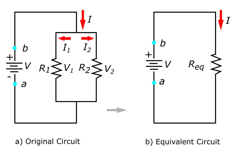
(b) The original circuit is reduced to a voltage source and equivalent resistance (combination of all parallel resistances).
In Figure 2, the current flowing through the circuit from the voltage source(battery) depends on the voltage being supplied and the combination of the parallel resistances of the circuit. In such a circuit, the current flows from the battery and enters the electrical node or junction (where the circuit splits), the current then splits to flow through resistors R1 and R2. This means that as the charges flow from the voltage source(a-b), some will flow through resistor R1 while the rest will flow through resistor R2. As mentioned earlier, the sum of currents flowing into the node should be equal to the summation of the currents flowing out of the node. This can be expressed mathematically as: Σ Iin = Σ Iout
The above equation is known as the Kirchhoff’s junction rule. In Figure 2, we can obtain the circuit using the junction rule as: I = I1 + I2. Since the circuit has two loops, we can formulate the following two equations by applying Ohm’s law (I = V/R); V=I1R2 and I1R1 = I2R2. Note the voltage across each resistor connected in parallel is the same (V =V1 = V2), while the current is additive:
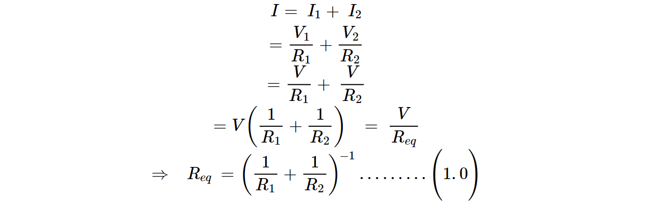
Addition of parallel resistances provides a value known as Conductance, which is symbolized by G and its units being the Siemens(S). Conductance is the inverse or reciprocal of resistance given as G = 1/R. Hence, the inverse of conductance gives us the equivalent resistance (Req) of all the resistors connected in parallel.
If we generalize Equation 1.0 to any number N of Resistors connected in parallel, the equivalent resistance of the resulting parallel configuration is calculated using this formula:
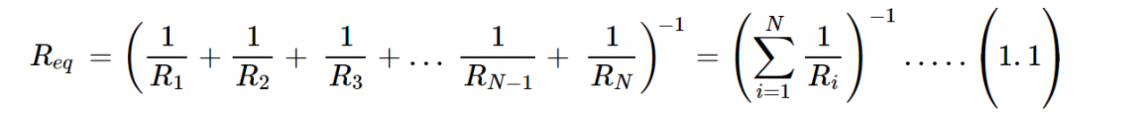
where:
- Req is the equivalent parallel resistance
- R1, R2, …RN are the resistances of individual resistors connected in parallel numbered 1 …N
The relation in Equation (1.1) results in an equivalent resistance value Req, which is less than the smallest value of the individual resistances. This means that when resistors are connected in parallel, the total resistance will be lower, thus, more current flows from the source than would flow if it was just one resistor used in the circuit. If for example, you apply a certain voltage across a resistor, a given amount of current will flow. If you add another resistor in the circuit and connect it in parallel with the first one, you will have essentially opened a new pathway through which more current can flow. Even if the second resistor will have much higher resistance, the total current supplied by the voltage source will be at least slightly higher than when only one resistor was connected.
Analysis of a Parallel Resistive Circuit
In this section, we’ll look at a few examples on how to calculate Parallel Resistance using the formula given in Eqn. (1.1).
Example 1: Suppose three resistors are connected in parallel, and their individual resistances are: R1= 1.00 Ω, R2= 3.00 Ω, and R3= 2.00 Ω. The parallel resistor connection is attached to a voltage source V = 3.00 V. What is the equivalent resistance of this resistive circuit?
Solution: The total resistance or equivalent resistance for a parallel combination of resistors is obtained using Equation (1.1). By substituting the values of the individual resistances in the equation, we get:

The total resistance of such a resistive circuit is Req = 0.5455 Ω. As stated earlier, the value of Req is less than the value of the smallest individual resistance.
Example 2: If the output voltage of a battery connected to a resistive circuit with four resistors connected in parallel is 12.0V, and their individual resistances are R1= 2.00 Ω, R2= 6.00 Ω, R3= 13.00 Ω, and R4= 3.00 Ω. Calculate the total parallel resistance of the circuit.
Solution: The total resistance will be given as:

The total resistance of the circuit is Req =0.9286 Ω , which is less than the value of the smallest individual resistance in that circuit.
Parallel Resistance Calculator

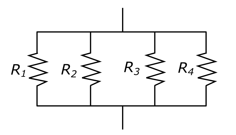
Calculating the equivalent resistance of resistors connected in parallel by hand can be very tiresome; especially when you have multiple resistors connected in complex configurations as shown to the right.
The common rule is that when resistors are connected between the same two points or across each other they are said to be in parallel. But as shown in the diagram above, a parallel resistive circuit can take various forms than the obvious. Also, you can include as many resistors as per your application needs and other electrical constraints.
The Parallel Resistance Calculator was designed to quickly calculate the total parallel resistance of a resistive circuit with a minimum of two and a maximum of six resistors connected in parallel. It is thus a tool used to determine the equivalent resistance (Req) of an electrical circuit with up to six resistors in parallel. It provides an easy and faster method for calculating the overall parallel resistance.
The Parallel Resistance Calculator operates in two different modes. The first mode enables you to calculate the equivalent resistance (Req), for a combination of individual parallel resistances. In contrast, in its second operational mode, it will enable you to set the desired value for the equivalent resistance of a given number of resistors connected in parallel, and calculate the missing resistor value, when the rest are provided.
How to use the Parallel Resistance Calculator
To use the Parallel Resistance Calculator as shown at the top of the page, you will first need to specify the number of parallel resistors and their individual resistances. After you have determined those values, the next thing will be to enter the values for resistors R1, R2, …R6 in the input boxes provided in the calculator, depending on the number of parallel resistors in your circuit. Then, press ‘calculate’ and the equivalent resistance will be provided.
If for example you have more than 6 resistors connected in parallel, simply use the calculator to find the total parallel resistance of the first 6 resistors. Then enter the resulting equivalent resistance value in for R1 and add the values for R7, R8, …, R11 into the calculator in the R2, R3, … R6 input fields. If the resistors are more than 11 in number, repeat the process again. Note you can enter the values of resistors R1, R2, …R6 in either ohms(Ω), Megaohms(MΩ) or Kiloohms(kΩ). The Parallel Resistance Calculator will always provide the equivalent resistance in the same units as the input. Even so, all the resistor values you input should be in the same units. Also, the Parallel Resistor Calculator operates on the same principle as when determining induction in parallel connections. You can therefore use it for induction calculations, only that the units won’t be the same.
The Parallel Resistance Calculator is useful in determining the overall resistance of resistors connected in parallel, even when they are more than six. But the calculator is more useful when you’re designing an electrical circuit that requires a specific resistance value and you don’t have an appropriate ohmic device readily available. For example, if your LED circuit requires about 500 Ω to attain the desired brightness and you intend to connect three resistors in parallel to achieve the total resistance value, but you only have a 300 Ω and a 700 Ω resistor. The Parallel Resistance Calculator will enable you to easily calculate the value of the third resistor, to get the 500 Ω LED circuit.
Example of finding a missing resistor value:
- On the settings of your Parallel Resistor Calculator, select “Calculate Missing Resistor” under the second Mode.
- Input the value of the total resistance you would like your resistive circuit to have in a parallel configuration.
- Start by entering the values of the resistors that are already known, new input fields will continue appearing as needed.
- Then press “calculate”; the calculator will automatically provide the required missing resistor value.
- You can press “reset”, and enter all the values of the individual resistances accordingly, to confirm that the resulting equivalent resistance is as you intended.
Keep in mind that the current flowing through each resistor does not change whenever more resistors are added in parallel. This is because the voltage across the terminals is not affected by adding resistors in parallel, instead, the voltage remains constant. In contrast, what changes is the amount of current drawn from the power supply, but not the current passing through a particular resistor. So, if the overall resistance is lower, the total current delivered by the voltage source will definitely be higher.
For this reason, parallel resistive circuits are one of the two fundamental electrical circuit configurations you will come across every day. Similar to a parallel universe, parallel resistive networks and circuits can give unexpected results. Like adding more resistors in parallel results in less overall resistance, while the voltage remains constant all through. For more information or to discuss which products might be best for your industrial needs, please visit our website here, or contact us at sales@dosupply.com or +1 (919) 205-4392.
DO Supply Inc. makes no representations as to the completeness, validity, correctness, suitability, or accuracy of any information on this website and will not be liable for any delays, omissions, or errors in this information or any losses, injuries, or damages arising from its display or use. All the information on this website is provided on an "as-is" basis. It is the reader's responsibility to verify their own facts.