Capacitor Charge Calculator: What is Capacitor Charge and How is it Calculated?
Capacitor Charge and Time Constant Calculator
What is a Capacitor?
When it comes to electronic devices and electric circuits, energy is typically stored in either batteries or capacitors. Batteries store electrical energy in chemicals, and they are the most common. Capacitors on the other hand possess the ability to store electrical energy in the form of an electric charge, they are less common. Essentially, a capacitor is a two-terminal electrical device, which consists of two conductors with a spacing distance(d) between them. The spacing between the two electrical conductors can be a vacuum or it could be filled with a good insulating material called dielectric. Often, you’ll come across the term “capacitance” which is defined as the ability of a capacitor to store electrical charge.
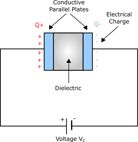
In its basic form, a typical capacitor is made up of two parallel metal (conductive) plates that are electrically separated either by a vacuum, air, or a dielectric; the separation ensures that the two plates don’t touch nor connect. The parallel plate capacitor (shown in the diagram to the right), is the simplest design for a capacitor. The general shape, construction, and size of a parallel plate capacitor depend on its voltage rating and application.
There are many other different kinds of capacitors built-in in many forms, lengths, styles, girths, and a variety of materials. For example, resonance circuits use very tiny capacitor beads whereas power factor correction capacitors are very large, though they all have the same functionality-storing electrical energy. Also, the dielectric material in a capacitor used can be either ceramic, mica, plastic, waxed paper, or some form of a liquid gel in electrolytic capacitors. Moreover, the conductive metal plates used may be either rectangular, circular, square, spherical, or cylindrical.
How Does a Capacitor Work?
To better explain how a capacitor works, let’s consider a basic parallel plate capacitor with two parallel conductive metal plates separated by a dielectric. When a DC voltage source is connected across the capacitor, such that its positive end is connected to Plate I and its negative end are connected to Plate II; as illustrated in the diagram below. The dielectric will block current flow through the capacitor because it is made of a non-conductive (an insulator), instead of allowing a voltage to be present across the two parallel plates in the form of an electrical charge.
However, when you connect a capacitor in an AC circuit or to an alternating current, the flow of current seems to pass through the capacitor with little or zero resistance(unimpeded). This explains why capacitors are only capable of storing electrical charges when connected to a DC voltage source.
Generally, there are two types of electrical charge, a negative(-ve) charge in the form of Electrons and a positive(+ve) charge in the form of Protons. So, with the DC voltage source placed across the capacitor, an electric field develops across the capacitor. This causes positive(+ve) charges from the battery to quickly accumulate on Plate I while corresponding opposite and negative(-ve) charges accumulate on Plate II, as illustrated in the diagram above. Therefore, Plate I become positively charged with respect to Plate II, which becomes negatively charged.
Note, for every particle of positive charge that arrives at Plate I, a charge of the same sign will depart from the negatively charged Plate II. The flow of electrons (-ve charge) onto the two conductive plates is known as the capacitor’s Charging Current. This current continues to flow until the voltage across Plate I and Plate II is equal to the voltage supplied by the DC source (Vc). After a period of time, the capacitor will hold a maximum amount of electrical charge as per its capacitance with respect to the applied voltage. This time span is referred to as the charging time of the capacitor and at this point, we can say that the capacitor is “fully charged” with electrons.
So, a capacitor stores energy by holding apart pairs of positive and negative charges. The two plates remain charge neutral and a potential difference(voltage) develops due to the charge established between the two conductive plates. Once the capacitor reaches its steady-state condition an electrical current tries to flow through the capacitor from its positive Plate I to its negative Plate II. However, this flow is not possible due to dielectric separation.
When the DC voltage source is disconnected from the capacitor, the two plates hold a positive and negative charge for a given time. Within that time, the capacitor can act as a source of electrical energy. If, however, you connect the capacitor to a load, the stored energy will flow as current to the load from Plate I to Plate II until both the positive and negative charges are dissipated from the two plates. This time frame is known as the capacitor’s discharging time.
The strength of the charging current of a parallel plate capacitor is said to be at its maximum value when the two conductive plates are fully discharged or at the initial condition. Its strength gradually reduces in value to zero as the two plates charge up to a voltage (potential difference) across the capacitor that is equal to the source voltage. Note, the amount of voltage generated across the capacitor depends on the capacitance of the capacitor and the amount of charge deposited onto the plates by the voltage supplied by the DC source.
Applications of Capacitors
The charging/discharging property of capacitors makes them very useful in a variety of applications in electrical engineering. Here are a few of them:
A) Flash Lamp: Capacitors are used to store an electrical charge for high-speed use in flash lamps. Normally, the circuit of a flash lamp consists of a huge high-voltage polarized electrolytic capacitor that stores the required charge. The stored electrical charge is then converted to several thousand volts within a very short time span to fire the flash lamp. Large lasers use the capacitor technique as well to generate very brightly, instantaneous flashes.
B) Surge Protector: Most consumer electronics like TVs, CD players, computers, and other sensitive instrumentation are fitted with line conditioners. In addition to protecting electronics from unexpected voltage and current surges, most quality power conditioners will also filter out Radio-Frequency Interference (RFI) and Electromagnetic Interference (EMI). This filtering is possible with the right combination of a capacitor and a resistor, which form an RC circuit. Consequently, the charging and discharging of a capacitor means that it will not allow spurious electric signals and rapid voltage spikes, which would otherwise damage sensitive electric circuits and components.
C) Power Conditioning: A major application of capacitors is in the conditioning of power supplies. When charged, capacitors are known to block DC signals but they allow AC signals. Hence, they can clean the supply of power by effectively splitting AC and DC signal types. This characteristic property of capacitors is highly utilized in separating or decoupling different parts of electrical circuits to eliminate/reduce electrical noise which could lower the circuit’s efficiency. Also, you will find capacitors in power utility substations where they are used to counteract inductive loading that is introduced by power transmission lines.
D) Signal Processing: The information technology sector is one of the industries that are increasingly adopting capacitor technology for advanced applications. For instance, electronic devices with Random Access Memory (DRAM) use capacitors to represent the binary information in form of bits. When the capacitor is fully charged the DRAM device reads a given value and when discharged the device reads another. Capacitors are also used in analog form in Charge-Coupled Devices (CCDs). Moreover, capacitors are used together with inductors to tune electrical circuits to specific frequencies, an effect that’s highly exploited in analog equalizers, speakers, and radio receivers.
E) Sensors: Sensors consisting of capacitors are used to measure a variety of physical quantities like mechanical strain, fuel levels, and air humidity. Two aspects of capacitors that make them useful in sensing applications include the dielectric material between them and the distance between the two parallel plates in the case of parallel plate capacitors. For instance, air humidity sensors are based on the fact that even minute changes in the amount of dielectric material between the plates are enough to alter the capacitance of the sensor device.
What is Capacitor Charge?
As discussed in the previous sections, a capacitor is a device that stores energy in the form of electrical charge and it consists of two conductive metal plates in close proximity but separated by a dielectric material. Such that whenever you connect a DC voltage to a capacitor, an electric field will develop across the dielectric material, causing the positive charges(+Q) to accumulate on one plate and negative charges(-Q) to accumulate on the other plate. If positive charges with charge +Q collect on one of the conductive plates and an equal number of negative charges with total charge -Q collect on the second conductor, we can say the capacitor has charge Q. This charge Q is referred to as Capacitor Charge. The capacitor charge or rather the electrical charge stored by the capacitor is denoted by Q and is measured in Coulombs(C).
Note, the ability of the capacitor (whose capacitance in Farads is known) to store electrical charge(Q) between its conductive plates is proportional to the supplied voltage V. Also, the larger the area of the plates and/or the smaller the separation between the plates the greater the electrical charge that the capacitor can store and its capacitance will definitely be high.
How is Capacitor Charge Calculated?
The electrical charge stored on the conductive metal plates of a parallel plate capacitor is directly proportional to the voltage supplied by the DC source. This can be expressed as:
V ? Q
where,
V = Voltage
Q = Capacitor Charge
Capacitor Charge Equations
From the relations between the Capacitance (C), Voltage (V) and Capacitor charge (Q) we can formulate the capacitor charge formula in three equations:
C = Q / V ; Q = C × V ; V = Q / C
The first equation illustrates how you can find the capacitance based on Voltage and Charge, the second one is the Capacitor Charge equation and the third one is called the Capacitor Voltage equation. Where:
Q = Charge, in Coulombs
C = Capacitance, in Farads
V = Voltage, in Volts
It is often easier to remember the above relations through pictorial representations, as illustrated in the images below.
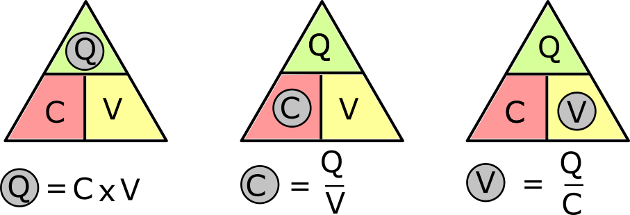
The three quantities (V, Q, and C) are superimposed into a triangle format with the capacitor charge at the top while voltage and capacitance at the bottom. So, you can determine the amount of charge stored in a capacitor using the Capacitor Charge equations explained above.
Capacitor Charge Calculation Examples
Example 1: A voltage of 50Mv(millivolts) is applied to a capacitor on a computer motherboard whose capacitance is known to be 5 Farads. Calculate the Capacitor Charge.
Solution: In this case we already know the values of Capacitance and Voltage. So, we’ll use the equation for calculating the Capacitor Charge, given as: Q = C × V. Where C = 5F, V = 50mV which can be converted to volts to give us V = 0.05V. Hence, Q = 5F × 0.050V = 0.25C (Coulombs).
Example 2: A electronic circuit has a capacitor with 100 µF (Microfarad) capacitance, and a voltage source of 15V. What is the amount of charge stored by the capacitor?
Solution: First, we convert the capacitance value from Microfarads to Farads, to get C = 0.0001F. Then using this equation: Q = C × V, the amount of Capacitor Charge is found to be Q = 0.0001F × 15V = 0.0015 C (Coulombs).
Capacitor Charge Calculator
The Capacitor Charge Calculator is a tool that has been developed to easily compute the charge of the capacitor given the applied voltage and its capacitance. It supports multiple measurements units for inputs including mV, V, kV, MV, GV, mF, µF, F…etc. As well as a variety of output units including C (Coulombs), kC (Kilocoulombs), MC (Megacoulombs)…. etc.
Our Capacitor Charge Calculator calculates the energy of the capacitor in addition to calculating the capacitor charge. The energy (E) of a capacitor is defined as the amount of work that the stored electrical charge can perform. It is measured either in electron-Volts (eV), Joules (J), or Calories (Cal). Likewise, such calculators support multiple units of measurements for energy output including J, kJ, MJ, Cal, kCal, eV, keV, etc.
This tool will function both as a capacitor charge calculator and a capacitor energy calculator. The required inputs are the same for both cases: the voltage(V) applied to the capacitor and the capacitance(C). This dual-calculator supports a broad range of input and output measurements. Also, it’s a very easy to use calculator, as you simply enter the voltage and capacitance values and select the outputs units for both capacitor charge and capacitor energy. Alternatively, you can use the calculator’s default units.
Note, the calculator uses conversion operations, the capacitor charge equations explained above and the capacitor energy equation given as: E = ( C × V2 ) / 2, where E is the energy which can also be written as work (W), C is capacitance and V is voltage.
DO Supply Inc. makes no representations as to the completeness, validity, correctness, suitability, or accuracy of any information on this website and will not be liable for any delays, omissions, or errors in this information or any losses, injuries, or damages arising from its display or use. All the information on this website is provided on an "as-is" basis. It is the reader's responsibility to verify their own facts.