Stepper Motor Calculator
Stepper Motor Calculator
|
Watts
|
|
|
ms
|
|
|
revolutions/second
|
A stepper motor is simply an electromechanical device that converts electrical power into mechanical power. It is a popular type of brushless, synchronous electric motor that converts input discrete(digital) pulses into mechanical shaft rotations. It divides a full shaft rotation into an expansive number of precise movements called steps.
If you drive a stepper motor using a DC power supply that is sequentially switched, then the rotor shaft of the stepper will consist of discrete angular movements with uniform magnitudes. Unlike other standard types of DC (Direct Current) motors which rotate continuously for an arbitrary number of spins until the DC voltage being supplied is turned off.
Stepper motors are a type of discrete input-output device for precise starting and stopping. They’re particularly suited for applications where control signals are digital pulses instead of analog voltages. One digital input pulse to a stepper motor translator or drive causes the motor rotation to increment by one precise angle of motion. But if you continuously increase the frequency of the digital pulses, the step movements will change into continuous rotation.
Construction & Working Principle of Stepper Motors
Construction
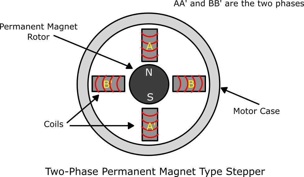
The structure of a stepper motor is fairly related to that of a standard DC motor, with a moving part (the rotor) and a stationary part (the stator). Similarly, a stepper motor includes a rotor located in the middle, and a number of stator poles enclosing the rotor. The rotor is the rotating shaft which can either be a variable reluctance iron core or a permanent magnet. The stator forms the stationary part, and on it, there are teeth(poles) on which electromagnetic coils are wired all over it. Stepper motors have multiple coils which are organized in groups called “phases”. The figure below shows the cross-section of a typical stepper motor, whose rotor is a permanent magnet.
Working Principle
The fundamental working principle of a stepper motor is Electro-Magnetism based on the theory of operation of magnets. Once discrete DC voltage is applied to the winding of the stator, one or more of the stator phases gets energized and a magnetic field is generated by the current flowing through the stator coil. The rotor aligns with this magnetic field, which causes it to rotate at a particular angle referred to as the step angle. By energizing different stator phases in sequence, you can make the rotor move by a specific number of steps (one step at a time) to reach the desired final position.
Stepper motors are usually manufactured with 12, 24, 72, 144, 180, and 200 steps per revolution and a corresponding step angle of 30º,15º, 5º, 2.5º, 2º, and 1.8º. You can operate a stepper motor with or without feedback control. When operated without feedback control, the stepper motor can be controlled by energizing every stator phase one by one. So, the stator’s alternative magnetizing and demagnetizing will gradually shift the rotor, allowing it to turn through great control. Note, you can also accurately control the motor’s position without any feedback mechanism, as long as you properly size it for the given application.
Types of Stepper Motors
Based on the type of material used to make the rotor, there are three main types of stepper motors, namely:
A) Permanent Magnet (PM) Steppers: The rotors of these stepper motors are constructed using Permanent Magnets. They operate on the attraction or repulsion between the rotor’s PM and the stator electromagnets to create rotation and torque. They can produce more torque per unit of input power and they usually have comparatively low input power requirements. Digital pulses move the rotor in discrete steps, either Clockwise (CW) or Counter-Clockwise (CCW). They are the most common type of stepper motors available in the market.
B) Variable Reluctance (VR) Steppers: They are built with a plain iron rotor and they resemble a gear, with “teeth” or protrusions around the circumference of the rotor. They operate based on the principle that with a minimum gap you can achieve minimum reluctance. Hence, the rotor poles are attracted towards the stator electromagnetic poles. This makes VR stepper motors capable of achieving a very high degree of angular resolution but at the expense of output torque.
C) Hybrid Synchronous (HS)Steppers: The rotor of an HS motor is constructed with a permanent magnet core, while its circumference is built with plain iron and it has teeth. HS motors combine the best features of VR and PM steppers to achieve maximum power in small packages. They are characterized by high angular step resolution, high speed, and higher torque than PM and VR steppers. HS motors are more expensive and they’re mainly used in applications requiring less stepping angle such as 2.5º, 1.8º, and 1.5º.
Applications of Stepper Motors
A) Positioning: Stepper motors move in precise repeatable steps and with computer-controlled stepping you can achieve very precise positioning. For this reason, they are categorized under motion-control positioning. They excel in devices that require precise positioning such as 3D printers, Scanners, X-Y Plotters, Camera Platforms. Also, to position the read/write head, some disk drives use stepper motors. Similarly, stepper motors are used in precise fluid control devices particularly in positioning valve pilot stages.
B) Low Speed Torque: Standard DC motors don’t give much output torque at low speeds. But stepper motors provide maximum output torque at low speeds. So, they’re an ideal choice for applications that require low speed but with high precision. They are often part of linear actuators, rotation, and goniometers stages in the field of optics and lasers where low speed and precision positioning is often required.
C) Speed Control: Stepper motors allow very small and precise increments of movements. And with computer controlled stepping you can achieve excellent control of rotational speed for Process automation (i.e., automated wire cutting), robotics, and packaging machinery (i.e., pick and place machines).
Limitations of Stepper Motors
A) Low Efficiency: Stepper motors have low efficiency because their current consumption is independent of the load. They also consume more energy than other normal DC motors. In addition, they draw more current when they’re not doing any work. Due to this, they tend to run hot or overheat.
B) Limited High-Speed Torque: Stepper motors generally have reduced torque at high speeds than at low speeds. But some steppers are optimized to perform better when used in high-speed applications. Though in such cases the stepper should be paired with an appropriate driver to achieve high-speed performance.
C) No Feedback Mechanism: Although stepper motors can operate in open-loop control systems and achieve great precision, they don’t have an integrated feedback system for positioning and speed control. Because of this, ‘home’ detectors and limit switches are required for safety and to establish a reference position.
Stepper Motor Calculations
The performance of a stepper motor is determined in terms of three key parameters namely: Maximum Power Dissipation, Maximum Speed, and Minimum Time Per Step. These parameters are computed as follows:
A) Maximum Power Dissipation
The maximum power dissipated by a stepper motor can be calculated using the following formula:
Pmax = Imax × U ……… (i)
Where:
Pmax = Maximum Power Dissipated
Imax = Maximum Current
U = Applied Voltage
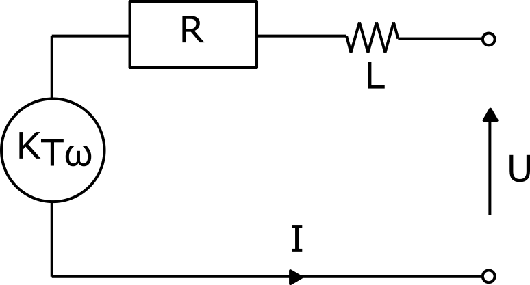
The maximum current (Imax) is a specification available in the data sheet provided by the stepper motor manufacturer. To understand how the applied voltage (U) is calculated, let’s consider the schematic of a stepper motor shown below:
From the schematic to the right, KTω represents a torque-speed factor, R is electrical resistance of the windings and L is the inductance of the windings. I is the current in the motor windings, and U is the applied voltage which is calculated as:
U = RI + KTω(t) + [ L ( dI / dt ) ] ……… (i)
Where:
RI = Voltage to drive current, given by Resistance (R) multiplied by the current in the windings (I)
KTω(t) = Voltage used to compensate the back-EMF1, where KT is the torque constant and ω(t) is the speed of the stepper motor
L ( dI / dt ) = Voltage required to establish or modify the current level
In an ideal stepper motor, the torque (T) is directly proportional to the current in the windings. This can be expressed as:
T = KT × I ……… (ii)
Also, the torque equation for no deceleration or acceleration (constant torque) is:
TJ ( Torque in mN.m ) = JT × ( v2 / 2 ) × K ………(iii)
Whereby:
JT = Total inertia in ( g.m2 ), given as: JT = JR + JL
JR = Motor Rotor Inertia ( g.m2 )
JL = Load Inertia ( g.m2 )
v = Rate of steps/second
K = Radians/second, given as: K= [ ( 2π ) / ( steps / revolution ) ]
Example: A stepper is to be used to drive a tape capstan. The inertia of the capstan is 10 × 10−4 g. m2 (gram meter squared) and the drag torque (TF) is 15.3 mN.m (millinewton−meter). The capstan is supposed to rotate at a rate of 200 steps per second in 7.5° increments. Calculate the overall output torque of the stepper motor, consider a 57L048B motor in which for 7.5° step angle there is 48 steps/revolution.
Solution:
Overall torque output (T) = TJ + TF
TJ = JT × ( v2 / 2 ) × K
JT = JR + JL = 34 × 10−4 + 10 × 10−4 = 44 × 10−4 g. m2
K = [ ( 2π ) / ( steps / revolution ) ] = ( 2π ) / ( 48 ) = 0.1309 radians/sec
TJ = 44 × 10−4 g. m2 × ( 2002 / 2 ) × 0.1309 = 11.52 mN.m
T = TJ + TF = 11.52 mN.m + 15.3 mN.m =26.82 mN.m
Let’s get back to calculating the maximum power dissipated by a stepper motor, computed using eqn.(i).
Example: Calculate the maximum power dissipated by a 4-wire stepper motor with catalog 17HS19-2004S1. The motor is connected to a 24V power supply. The current in the stepper driver is limited to 1.5A. Given that:
Rated Current/phase = 2.0A
Rated Voltage/phase= 2.8V
Recommended Voltage = 12-24V
Solution: For this example, we’ll use equation (i)
Pmax = Imax × U ……… (i)
where: Imax = 1.5A, U = 24V, which is the actual voltage or applied voltage.
Hence, Pmax = 1.5A × 24V = 36W
Stepper motors are often operated at voltages higher than their rated voltage. This may not necessarily be the case for very small steppers, but high torque stepper motors must run at higher voltages so that they can reach their full potential. Increasing the applied voltage increases the rate at which the current in motor windings rises. The higher the responsivity of the current in the windings, the more torque and speed characteristics of the motor.
As a result, the current in the windings can be obtained using this equation:
I = [ U − KTω(t) − (L (dI / dt)) ] / (R) ⇒ I = ( U / R ) x ( 1 − e−(R/L)t ) − ( KTω(t) / R ) ………(iv)
From the above equation (eqn. iv), we can conclude that the factors which influence the current, and hence the output torque of a stepper motor are:
- Inductance ( [ L ( dI/dt ) ], L = winding inductance). It prevents the current from establishing rapidly in the phases.
- Resistance (R = winding resistance). It influences the maximal current set in each phase.
- The back EMF. When the speed (ω) is increased, the back-EMF proportional to KTω(t) also increase while the current in the windings decreases, this causes the output torque to reduce as well. This is why you’ll find that regardless of the operation mode of the motor, torque will always decline when motor speed increases as observed in the torque/speed curves provide in a stepper motor data sheet.
Note, stepper motors can be driven in two different sequences namely:
- Full Step Sequence: In this mode, two stator coils are energized at the same time which makes the motor shaft to rotate.
- Half Step Sequence: In this mode, the motors’ step angle reduces to half the step angle in full mode operation. Hence, the angular resolution increases by twice the angular resolution in full mode. Also, the number of steps gets doubled in half mode as that of full mode. Usually, half mode is more preferred over full mode.
Phases, Poles and Step Angle
Stepper motors usually have 2 phases, though some of them may also have 3 or 5 phases. Bipolar stepper motors normally use one winding per phase, because it is possible to make the current in the single winding circulate in both directions. In contrast, Unipolar stepper motors also use a single winding per phase but they have a tap in the middle; thus, you can use half of the winding for positive current flow and the other to allow negative current flow.
A pole in a stepper motor is defined as the region with the maximum concentration of magnetic flux density. Stepper poles correlate with the South or the North “pole” of a magnet. You’ll often come across stepper motors featuring either 5 or 6 pole pairs (corresponding to 10 or 12 poles) in combination with 2 phases, this leads to 20 or 24 steps per revolution.
Steps per revolution = no. of poles x no. of phases
With the number of steps, you can determine the step angle as:
Step Angle = [ 360 / ( Nph × Ph ) ] = [ 360 / N ]
Where:
Nph = Number of rotor poles = Number of equivalent poles per phase
Ph = Number of phases
N = Total number of poles for all phases combined
Example: A Stepper Motor operating in full mode takes 4 steps to complete a single revolution. Calculate its Step Angle.
Solution:
Step Angle = [ ( 360 ) / ( Nph × Ph ) ] = [ ( 360° ) / ( 4 × 1 ) ] = 90°
In case of half mode, the step angle will be:
Step Angle = [ ( 360 ) / ( Nph × Ph ) ] = [ ( 360° ) / ( 4 × 2 ) = 45°
B) Maximum Speed
RPM (revolutions per minute) is the measure used to describe the speed of an electric motor. It describes the rate at which the motor’s rotor is revolving, and it’s usually represented by ω. Stepper motors have drive circuits that emit command input pulses at specified rates. Each pulse moves the rotor one step, this means that “pulses per second” readily translates to “steps per second”. As previously noted, the number of steps required to complete one rotor revolution varies.
The number of revolutions per second is thus given as:
Revolutions per second = ( steps per second ) / ( steps per revolution )
While the number of revolutions per minute, or RPM (speed of the stepper motor), is:
RPM = ( steps per second / steps per revolution ) × 60
Example: If your stepper motor has a command pulse rate of 30 per second and a step angle of 0.72o. What is its RPM?
Solution: Let’s first find the no. of steps/revolution, using:
steps / revolution = ( 360° / step angle ) = ( 360° / 0.72° ) = 500
Hence, the motor speed (ω) will be:
ω = ( steps per second / steps per revolution ) × 60 = ( 30 / 500 ) × 60 = 3.6 RPM
However, a slightly different formula is used to calculate the maximum speed of a stepper motor. This formula is expressed as:
ωmax = U / ( 2LImax × spr )
Where:
ωmax = Maximum Speed of the stepper motor
U = Actual applied Voltage
spr = Steps per revolution
Imax = Maximum specified current
L = Winding Inductance
Note, the maximum speed of a stepper motor is limited by the time the stator coil takes to energize to its maximum holding current, and later de-energize as polarity changes.
C) Minimum Time per Stop
The minimum time a stepper motor takes to move one step is given by:
Minimum Time per Step = ( 2 × L × Imax ) / U
Where:
U = Applied Voltage
Imax = Maximum specified current
L = Winding Inductance
Stepper Motor Calculator
This is a tool developed to calculate the Maximum Power dissipated by a stepper motor, its Maximum Speed, and the Minimum Time per Step. It’s based on the equations described in the above sections.
Maximum Current (Imax), Inductance (L), Applied Voltage (U) and Steps per Revolution (spr). After that, select the appropriate units for each of the values entered. Note, the SI units for Current = Amperes (A), Inductance = Henry (H), and Applied Voltage = Volts (V); thus, you can input the values of these parameters in different variables. While Steps per Revolution = no. of steps.
For the values entered in the above calculator, the stepper motor parameters had been specified as follows:
| Parameter | Value |
| Fundamental Step Angle | 1.8°1.8° (Full Step) |
| Step Motor Type | Bipolar, 2 Phase |
| Rated Voltage | 4.25 V DC/Phase |
| Rated Current | 0.5 A DC/Phase (constant in the range of -10~50℃~50℃) |
| Winding Inductance | 4.1 mH/Phase |
| Winding Resistance | 8.5 Ω/Phase |
| Rotor Inertia | 1.6 ×10⁻⁷ Kg.m21.6 ×10−7 Kg.m2 |
Sample Specifications of a Stepping Motor
Hence, steps/revolution (spr) = ( 360° / Step angle ) = ( 360° / 1.8° ) = 200
U = 4.25 V (Assumed to be the applied Voltage)
spr = 200
Imax = 0.5 A
L = 4.1 mH
DO Supply Inc. makes no representations as to the completeness, validity, correctness, suitability, or accuracy of any information on this website and will not be liable for any delays, omissions, or errors in this information or any losses, injuries, or damages arising from its display or use. All the information on this website is provided on an "as-is" basis. It is the reader's responsibility to verify their own facts.