Tank Circuit Calculator
Tank Circuit Resonance Calculator
|
|
What is a Tank Circuit?
A Tank circuit is also called an LC circuit, a resonant circuit, or a tuned circuit. It is an idealized RLC electric circuit with zero resistance. It consists only of an Inductor (L) and a Capacitor(C), connected in a series or parallel configuration; hence the name LC circuit. Tank circuits are particularly useful due to their resonance property. They are implemented in a variety of electrical applications, such as frequency tuners, filters, and oscillators.
In any AC (Alternating Current) circuit containing Resistance(R), Capacitance(C), and Inductance(L) elements, the voltage phase across the circuit and the current phase in the circuit are generally different. But if you adjust the parameter values of the L or C components or the power supply frequency, you can make the voltage and current have the same phase, and the entire AC circuit will appear to be purely resistive. When the circuit gets to this state, it’s said to be at resonance, hence the name resonant circuit.
The operation of this circuit is analogous to that of a tank in a fluid system, in which the tank dimensions define the observed natural frequency; whenever fluid is pulsed through the tank. Similarly, the tank circuit stores energy oscillating at its resonance frequency. This is explained by the fact that capacitor electrodes store electrostatic energy according to voltage changes across the circuit. While the electromagnetic energy stored in the inductor’s magnetic field changes as per the current flowing through the inductor.
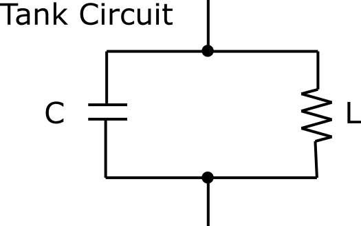
Tank Circuit Diagram
The circuit diagram of a tank circuit with an Inductor and a Capacitor in a parallel configuration is as shown to the right.
Inductors store electrical energy in magnetic fields, and the stored energy is proportional to the square of the current in the circuit. While capacitors store electrical energy in electric fields, the stored energy is proportional to the square of the voltage across the circuit. So, when an inductor and capacitor are connected together, their complementary energy storage modes cause electrical energy to be transferred back and forth between the inductance and the capacitance: with both current and voltage oscillating sinusoidally. This cyclic exchange of energy is referred to as resonance. And the simplest resonant circuit is the tank circuit, comprising of a single capacitor connected to a single inductor as shown above.
Note, tank circuits don’t use electrolytic capacitors as both sides of the capacitor must be charged, instead, they use ceramic capacitors. This is because the leads of ceramic capacitors don’t get polarized, so charging can take place on both capacitor terminals. However, with electrolyte capacitors, the leads get polarized and charging can take place on one side only.
How Does a Tank Circuit Work?
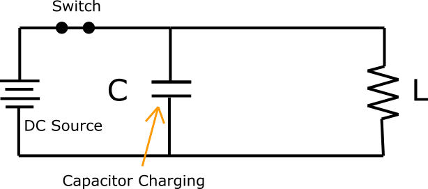
To understand how a tank circuit works, let’s us assume that the capacitor is already charged by a DC power source and its polarity is as shown in the diagram to the right.
The upper plate of the capacitor is positively charged in relation to the lower plate. This means that the capacitor has electrostatic energy and there’s the voltage across its terminals. When the SW switch in Figure 2 is closed (or the power source in Figure 1 is disconnected), the capacitor will start discharging with the charge traveling between its electrodes through the inductor coil. The direction of the current flow is indicated in the figure to the left.

The upper plate of the capacitor is positively charged in relation to the lower plate. This means that the capacitor has electrostatic energy and there’s the voltage across its terminals. When the SW switch in Figure 2 is closed (or the power source in Figure 1 is disconnected), the capacitor will start discharging with the charge travel because the inductor coil actually has an internal resistance, it won’t allow all of the current instantly. Instead, the current will build up gradually towards the maximum value. This gradual current flow creates a magnetic field, thereby generating an electromagnetic field around the inductor coil.
Eventually, all the electrostatic energy stored across the capacitor is released and converted into electromagnetic energy which is stored around the inductor. So once the capacitor is fully discharged, such that the voltage across the inductor is more than the voltage across the capacitor, the inductor’s magnetic field will start to collapse. This produces counter EMF and as per Lenz’s law, the counter EMF will keep the current flowing. Given that the function of the inductor in a tank circuit is to prevent current changes, extract electromagnetic energy from the generated magnetic field, and try to make the current flow as constant as possible.
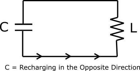
As the inductor dissipates its energy to the capacitor, the current gradually accumulates in the capacitor, and it becomes charged up in opposite polarity to before. As shown in the figure to the right: ling between its electrodes through the inductor coil. The direction of the current flow is indicated in the figure to the right.
When the magnetic field around the inductor disappears, the current flow stops and the capacitor returns to its original charged state though the voltage is applied with opposite polarity to before. When fully charged, the capacitor will again start discharging through the inductor coil. This whole process is continuously repeated until all the energy is dissipated by the resistance within the tank circuit.
Applications of Tank Circuits
Tank circuits have many important applications in the field of electrical engineering, these include:
- In Radio technology: The backward and forward movement of electrical energy through the capacitor and inductor produces an electromagnetic frequency. This frequency is very useful in telecommunications technology especially in radio transmitters and receivers. For example, the simplest radio transmitter consists of a class C amplifier having a tank circuit at its load side. So, when the amplifier circuit is powered, the tank circuit generates enough energy to couple the radio signal from the amplifier to the transmitting antenna which in turn radiates the signal into space.
- Similarly, a tank circuit is employed in radio receivers when receiving a signal. In such applications, once the tank circuit gets charged it generates a precise frequency, which tunes the radio receiver to the frequency of the signal being received. This exact resonance is useful in filtering out other frequencies (by blocking them), thus only selected radio stations can play. The technology is applicable in all communication devices like walkie-talkies, radio towers, etc.
- In Electronics: Tank circuits are employed to either select a given signal at a specific frequency from a more complex signal bandwidth (i.e., bandpass filters) or to generate signals at a particular frequency (as signal generators). In such applications, they play a key role in the operation of many electronic devices, including radio equipment and are utilized in a variety of electric circuits such as frequency mixers, oscillators, filters and tuners.
Tank Circuit Resonance Calculator
This is a tool designed and built to calculate the resonance frequency of a tank circuit when the values of Inductance (L) and Capacitance (C) are known.
As previously stated, the tank circuit is the most common type of resonant circuit. And in general, a resonant circuit absorbs maximum power at the resonance frequency. So, before diving into tank circuit Resonance Frequency Calculations, let’s first understand the resonance phenomenon and how the formula of resonance frequency comes about.
Resonance Phenomenon
Resonance occurs when the Capacitive reactance (XC) and the Inductive reactance (XL) of a tank circuit is of equal magnitude. So, at resonance, XC = XL. This phenomenon causes electrical energy to oscillate between the electric field of the capacitor and the magnetic field of the inductor. However, a tank circuit cannot resonate on its own, and an AC power source must be present or a similar power source such as radio waves.
Note: Resonance in tank circuits occurs because the collapsing inductor magnetic field produces an electric current in its windings which charges the capacitor, and the discharging capacitor provides an electric field that generates the magnetic field in the inductor- this process is repeated continuously.
It is also important to note that at resonance, the impedance of a series tank circuit (when L and C components are connected in series) is a minimum while the parallel impedance is at maximum.
Applications of Resonance Effect
- The most typical application of resonance in tank circuits is in signal adjustment. For example, whenever you’re tuning your radio to a specific broadcast station, the tank circuit resonates at the carrier frequency of that broadcast station.
- The series tank circuit increases the voltage. For this reason, Series resonant circuits are used as filter or sieve circuits. In such applications, the series oscillating circuit will allow frequencies close to the resonance frequency to pass.
- The parallel tank circuit increases the current. Thus, Parallel resonant circuits are mainly used as band-stop filters or trap circuits to filter out certain frequencies.
- The parallel tank circuit can be used in an RF (Radio Frequency) amplifier’s output circuit as the load impedance.
- Parallel resonant circuits are also widely used for induction heating
What is Resonance Frequency?
Resonant or Resonance Frequency is the frequency at which the values of inductance and capacitive reactance of a tank circuit are equal. In general, resonance frequency is a natural and undamped frequency of a system. Whenever resonance frequency is applied, oscillations attain maximum amplitude, and even relatively smaller forces are able to produce larger amplitudes.
However, if you choose another frequency other than the resonance frequency, that high amplitude signal will be dampened. There are plenty of different types of resonances including mechanical and acoustic, electrical, orbital, optical, and molecular resonances.
For Tank circuits, the resonant frequency is determined by the values of Inductance (L) and Capacitance (C). For this reason, whenever the inductor and capacitor components are connected in series or in parallel, they have a resonant frequency. And as previously stated, resonance in tank circuits occurs when XC = XL. This is because inductive reactance (XL) increases with increasing frequency, whereas capacitive reactance (XC) decreases with increasing frequency, and there’s only one frequency where the two reactance can be equal- which is resonance frequency.
The equations for determining inductive and capacitive reactance at a given frequency are as follows:
XL = 2πfL ……… (i)
XC = (1) / (2πfC) ……… (ii)
At resonance, XL = XC
We can then equate the two equations and solve them algebraically for resonance frequency. Hence,
2πfL = (1) / (2πfC) ………(iii)
Solving for f we get,
f2 = (1) / (4π2LC)
f = [1] / [2π √(L×C)]
Thus, the resonant frequency (fr) of a tank circuit is computed using the following equation:
fr = [1] / [2π √(L×C)] ………(iv)
Where:
fr = Resonance Frequency of a tank circuit, given in Hz (Hertz)
L = Inductance in Henrys (H)
C = Capacitance in Farads (F)
Note, the formula for calculating the resonance frequency of a tank circuit is universal for either a series or a parallel resonant circuit. This is because in both cases, at resonance, the Voltage and Current are in phase at the ohmic resistance. And the phase shift =0°. This results in resonance frequency given by the formula in equation (iv).
However, the impedance Z of a series tank circuit is smallest at the resonance frequency when XC = XL. Whereas, the impedance Z of a parallel tank circuit is greatest at the resonance frequency when XC = XL.
Also, tank circuit impedance at resonance can be expressed as: Z = √ [ R2 + ( XL − XC )2 ]
R = Resistance within the tank circuit
Since the phase of the voltage across the circuit is opposite and XC = XL; the two reactance values will cancel out and the following applies: Z = R
Examples of Resonance Frequency Calculations
Example 1: The Inductance and Capacitance values of a tank circuit are given as 35mH and 10μF, respectively. Determine the resonant frequency the circuit?
Solution: Given that,
L = 35 mH = 35 × 10−3 H
C = 10 μF = 10 × 10−6 F
And the Resonant Frequency formula is:
fr = [ 1 ] / [ 2π √(L×C) ] ………(iv)
Then,
fr = [ 1 ] / [ 2π √(LC) ] = ( 1 ) / ( 2π √[(35 × 10−3 H ) × (10 × 10−6 F )] ) = 269.0210 Hz
So, the Resonant Frequency of that tank circuit will be fr = 269.02 Hz
Example 2: Let’s say that you wish to determine the resonant frequency of an LC circuit which has an inductor rated at 3 mH, and a capacitor with a capacitance of 4 µF.
Solution: The resonant frequency (fr) of the circuit is computed as follows:
L = 3 mH
C = 4 µF = 4 × 10⁻³ mF
Hence,
fr = [ 1 ] / [ 2π √(L×C) ] = [ 1 ] / [ 2π √( (3 mH ) × (4 × 10⁻³mF) )] = 1.4529 Hz
Therefore, the resonance frequency of the LC circuit will be ≈ 1.45 Hz
Note: Whenever you’re manually computing for tank circuit resonance frequency (without using the resonance frequency calculator), ensure that you convert the units of the given parameters to SI units of Henrys and Farads, or ensure that the given values share a common SI unit variable such as micro (µ), milli (m), nano (n), etc. Otherwise, the fr results will be in accurate.
Example 3: The parameters of an electrical tank circuit are given as: inductance is 50 mH and capacitance is 8 μF. Calculate the resonance frequency of this circuit in MHz?
Solution:
The given parameters in this problem are:
L = 50 mH = 50 × 10−3 H
C = 8 µF = 8 × 10⁻⁶ F
The formula for resonance frequency is:
fr = [ 1 ] / [ 2π√(L × C) ]
Substituting the inductance and capacitance values in the above formula,
fr = ( 1 ) / ( 2π√[(50 × 10−3H ) × (8 × 10⁻⁶F)] ) = 251.6461 Hz
Hence, the resonance frequency of the tank circuit in MHz will be:
fr = 251.6461 Hz × 10−6 = 0.0002516 MHz
fr = 2.516 × 10⁻⁴ MHz
How to use a Tank Circuit Calculator
This calculator employs the values of Inductance (L) and Capacitance (C) of a tank circuit (either in series or parallel configuration) to compute the circuit’s resonance frequency (fr). Its working principle is based on the following formula: fr = (1) / (2π√[L × C])
The calculator provides the value of the resonance frequency in either TeraHertz (THz), GigaHertz (GHz), MegaHertz (MHz), KiloHertz (kHz), or Hertz (Hz).
Steps to use the Calculator:
You can use the calculator by simply following these three steps:
- Input the given Capacitor (C) and Inductor (L) values.
- Select the units of measurement for the given parameters and the Resonance Frequency unit you wish to use.
- Click the “Calculate” button and the resonant frequency value will be calculated in a flash.
Example: Using a Tank Resonance Calculator (shown above), determine the resonance frequency of a tank circuit whose Inductance (L) is 65 mH and Capacitance (C) is 10 μF?
Using the above calculator, the resulting resonant frequency of the tank circuit is: fr = 0.0001974 MHz, which can also be expressed as: fr = 197.4 Hz
Note: When using the Tank Circuit Resonance Calculator, you don’t have to change the units of the given inductance and capacitance values to common SI units’ prefixes.
Example: Given that a tank circuit has a resonance frequency of 300Hz, and if its capacitance value is 6 µF. What is the value of the circuit’s inductance?
Solution 1: Computing by hand,
The given parameters are:
fr = 300 Hz
C = 6 × 10⁻⁶ F
And since the formula for resonant frequency is: fr = ( 1 ) / ( 2π√[L×C] )
In order to obtain the inductance value, we can make L the subject in the above equation,
fr2 = (1) / (4π2 × L × C)
L = (1) / (4π2 × C × fr2)
Substituting the given values in the inductance formula above,
L = (1) / (4π2 × C × fr2) = (1) / (4π2 × [6 × 10−6 F] × 3002) = 0.04691 H
Hence, the inductance of that tank circuit will be ≈ 46.91 mH (milliHenries)
Solution 2: Using a Tank Circuit Calculator
You can simply determine the inductance value using the calculator by: (i) inputting the Capacitor and Resonance Frequency values; (ii) Selecting the appropriate units of measurement.
DO Supply Inc. makes no representations as to the completeness, validity, correctness, suitability, or accuracy of any information on this website and will not be liable for any delays, omissions, or errors in this information or any losses, injuries, or damages arising from its display or use. All the information on this website is provided on an "as-is" basis. It is the reader's responsibility to verify their own facts.