Sinking vs Sourcing in PLCs
In general, the concept of Sourcing and Sinking details a current flow relation between input and output devices of a control system and their power supply. This concept is based on the basic electrical theory, which states that; to complete an electrical circuit, the conventional current should flow from the DC+ terminal through a load to the DC- terminal. In that regard, the two terminologies (Sinking and Sourcing) apply only to DC input and DC output circuits. And not to AC circuits because of the reference to positive (+) and negative (-) polarities.
In PLC systems, the Sinking and Sourcing concept may be confusing to most people but it’s fairly a simple one. As Sink and Source logic circuits are mainly associated with digital PLC Input and Output (I/O) signals. A logic circuit is basically an electrical I/O circuit in which its output is a function of the input. Such circuits are defined by the type of components used and the direction of current flow. A simple logic circuit can consist of a single binary (ON/OFF) output and one or more binary inputs. It may include any binary electronic or electrical devices, including push buttons, switches, transistors, solid-state diodes, and relays.
Therefore sinking and sourcing terminologies in PLCs apply only to digital DC input and output logic circuits. In this article, we’ll discuss Sinking vs. Sourcing digital PLC I/O modules. But first, let’s review what digital PLC inputs and outputs are.
Digital PLC Inputs
Also referred to as discrete inputs, digital inputs are the most common types of PLC inputs because PLCs being digital devices themselves are able to easily process digital input signals. The concept of digital signals is based on the binary number system, which has only two possible digits- 0 or 1. With 0 indicating a LOW state and 1 representing a HIGH state. Hence, discrete PLC input signals are either LOW or HIGH. A PLC system uses these digital input signals to determine whether a given field input device is ON or OFF, CLOSED or OPEN, ACTIVATED OR DEACTIVATED, etc.
Examples of field input devices that provide discrete input signals to PLC systems include:
- Start/Stop Push Buttons: These devices function either by making or breaking contact. They are thus categorized as Normally Open (NO) or Normally Closed (NC). Connecting a NO push button to a PLC input module creates an open logic circuit with no electrical continuity, hence, the current does not flow. On the other hand, when an NC push button is connected to a PLC input module it shorts the connected terminals, thereby completing the logic circuit and creating electrical continuity which allows current flow.
- Selector Switches: These switches are used to make/break/change contacts in PLC circuits used to control mechanical or electrical devices. This is because selector switches are not only Normally Closed or Normally Open, but they have more than two contacts to select from. They are operated manually by turning either a rotary knob or lever to choose one of the many available positions. Selector switches are often used in electric fans for motors.
- Proximity Sensors: They are normally used to detect the presence or absence of different objects in a nearby locality without making contact. They accomplish this by determining the variations in the emitted electromagnetic fields or by detecting changes in the return signal of a beam of electromagnetic radiation (such as infrared). They provide binary output- HIGH or LOW, hence the name proximity switches. Different target objects are detected by different types of proximity sensors i.e. capacitive or inductive proximity sensors.
Digital PLC Outputs
PLC outputs are typically the control circuits of a PLC system, which give the PLC processor control over field output devices such as solenoid valves, electric heaters, motors, and pumps. Digital PLC outputs exhibit only two possible conditions, they thus provide an ON/OFF control scheme. There are three types of digital PLC outputs, namely:
- Relay PLC Outputs: These are voltage-independent PLC outputs, which can be used to control both AC (Alternating Current) and DC (Direct Current) field output devices. They have five contacts, of which two are for power supply and the other three include: COM (Common), NC (Normally Closed), and NO (Normally Open). The COM contact is the common terminal that connects either NC or NO contacts as per the given trigger. Relay PLC outputs can control up to 2 Amperes and they are usually used in applications requiring low resistance.
- Transistor PLC Outputs: These are voltage-dependent PLC outputs that can only control DC loads. PLCs using transistor outputs are normally utilized in switching operations that require faster switching speeds like controlling lights, and in low-power DC circuits such as inside microprocessors.
- TRIAC PLC Outputs: TRIAC stands for Triode for Alternating Current. It’s a solid-state silicon-based electronic switch, which is activated by a small control voltage from a controller like PAC or PLC. Triac outputs are mainly used to control low-power AC loads such as lighting systems, motor starters, and contactors. They function in a similar way as MOSFET (Metal Oxide Semiconductor Field Effect Transistor) transistors.
Sinking vs. Sourcing in PLCs
As previously stated, the concept of Sinking and Sourcing applies only to digital PLC I/O modules and not analog I/O modules. It’s therefore very important to have a solid understanding of these two terminologies whenever you’re selecting the type of input or output module to use in your PLC system. Simply put, the concept of sinking and sourcing in digital PLC I/O modules is all about defining the direction of conventional current flow in a logic circuit between two devices.
Consider the following illustration:
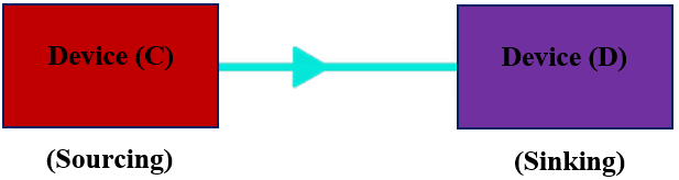
From the figure above, electric current is flowing from Device (C) to Device (D). Thus, Device (C) is the sourcing device because it sources current to Device (D), which in turn sinks that current. Device (D) is therefore the sinking device.
When current is flowing from Device (D) to Device (C), as shown below, then Device (D) is the sourcing device while Device(C) is the sinking device. The reason is Device (D) sources current to Device(C), which then sinks the received current.
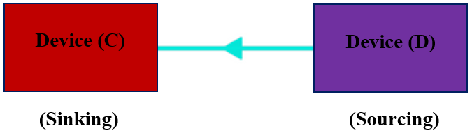
Note: In every DC circuit where you have current flowing between two devices, one of the devices will be the Sourcing device while the other will be the Sinking device.
In PLCs, a digital input module will detect one of the possible binary conditions of a discrete field input device such as either Closed or Open; Energized or De-Energized; ON or OFF; High or Low. And depending on the type of digital input module being used in the PLC system and its connection polarity to the field input device, DC current will either flow in or out of the input module. This is where Sinking and Sourcing terminologies come into the picture.
A Sourcing digital PLC I/O provides a voltage source for the external logic circuit, whereas a Sinking digital PLC I/O provides a ground connection for the external logic circuit. To better understand this concept, let’s see how digital PLC input modules detect the output conditions of digital field input devices; considering a Normally Closed (NC) Stop Pushbutton as the field input device of our PLC system.
Digital PLC Input Modules
Digital PLC input modules interface the PLC processor with field input devices. They monitor the conditions of field input devices such as switches, sensors, and start/stop push buttons and provide relevant information to the CPU regarding the status of those field devices.
A) Sourcing PLC Input Modules
As discussed earlier, Sinking and Sourcing relate to the direction in which conventional current flows between two devices in a logic DC circuit. Thus, based on the connection polarity between a digital PLC input module and a field input device; a Sourcing PLC input module will have current flowing out of its control terminal into the connected field input device. PLC vendors manufacture sourcing digital input modules by internally wiring their input cards to a voltage source, so the module can provide a positive voltage to an external logic DC circuit.
Consider the logic circuit illustrated below, whereby a digital PLC input module (labeled as Device #1) is connected to a Normally Closed (NC) Stop push button (labeled as Device #2).
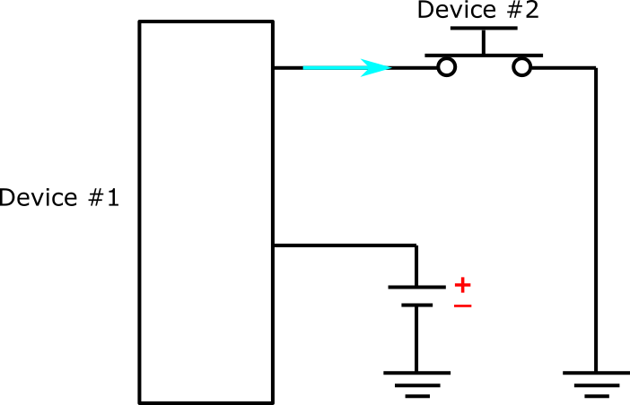
Let’s check the connection polarity between the two devices in Figure 1, to determine which device is the sourcing current and which one is sinking it. You can notice that the PLC input module (Device #1) is connected to the positive (+) terminal of a voltage source, presumably a power supply. Hence, it provides the positive voltage required to complete the logic circuit while the NC Stop Push Button (Device #2) provides the ground connection. An electric current is flowing from the control terminal of Device #1 into Device #2.
Thus, the digital PLC input module (Device #1) is the Sourcing device that sources current to Device #2. Then, the NC Stop Push Button (Device #2) transmits the received current to the ground, which makes it the Sinking device.
B) Sinking PLC Input Modules
Considering the connection polarity between a digital PLC input module and a field input device, a Sinking PLC input module has a current flowing into its control terminal. The input card of such a PLC module is internally wired to the ground. Thus, its internal circuit provides the necessary ground connection for the external logic circuit and a positive voltage is required to complete such a circuit.
To better understand the Sinking terminology in a PLC input module, consider the following diagram:
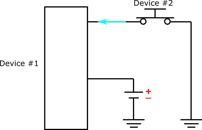
The logic circuit shown in Figure 2 includes a digital PLC input module (Device #1) and a Normally Closed Stop Push Button (Device #2) which is the field input device. Device #2 provides a positive voltage to the circuit since it’s connected to a power supply. Whereas, Device #1 which is internally connected to the ground provides a ground connection for the circuit.
Current is flowing from Device #2 to Device #1. Hence, Device #2(the NC Stop Push Button) sources current to the PLC input module (Device #1), which in turn sinks the received current into the ground. Thus, the NC Stop Push Button is the Sourcing device in Figure 2, while the digital PLC input module is the Sinking device.
Digital PLC Output Modules
The purpose of digital PLC output modules is to control or operate field output devices based on the conditions of the field devices connected to the PLC input modules and the execution results of a PLC program. They give the PLC processor control over connected physical devices like motors, electric heaters, pumps, solenoid valves, and relays.
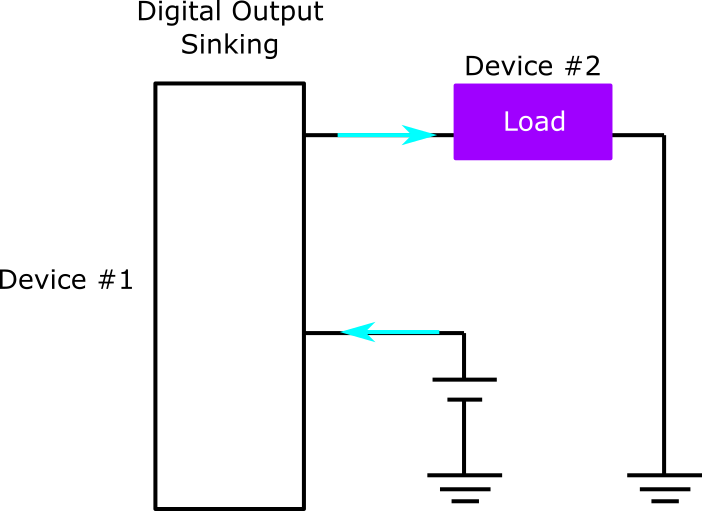
A) Sinking PLC Output Modules
If you recall, previously we said that the concept of Sinking and Sourcing is all about the direction in which conventional current flows. And when there are two devices with electric current flowing between them, one of the devices will be sourcing while the other one will be sinking the current.
Consider the circuit diagram in Figure 3, in which two devices have electric current flowing between them. One device is a digital PLC Output Module (labeled as Device #1) and the second device is a Relay Load (labeled as Device #2) – which represents a field output device.

Based on the connection polarity between the two devices, you can see that Device #2 is connected to a positive voltage while Device #1 is connected to the ground. Thus, current flows from Device #2 (the Relay Load) into the PLC Output Module (Device #1), which provides a ground connection for the circuit. Thus, the Relay Load (Device #2) is the Sourcing device in that logic circuit while the digital PLC Output Module (Device #1) is the Sinking device.
B) Sourcing PLC Output Modules
In this second example, shown in Figure 4, the electric current is flowing from the control terminal of the digital PLC Output Module (Device #1) into the Relay Load (Device #2). Thus, Device #1 sources current to Device #2 which makes it the Sourcing device. Whereas the Relay Load sinks the received current into the ground, this makes it the Sinking device.
A Quick Way to Identify a Sinking or Sourcing PLC Output Module
You might be wondering whether by just looking at a wiring diagram you can identify if a PLC output module is Sinking or Sourcing. Well, here’s a tip that might assist you: Each digital output module used in a PLC system connects directly to one terminal of each load. While the remaining terminals of each and every load are wired together. So, if the wired-together load terminals connect to the positive (+) terminal of the PLC system power supply, then you have a Sinking digital PLC output module. But if the wired-together load terminals are connected to the negative (-) terminal of the power supply (i.e. they provide a ground connection), then you have a Sourcing digital PLC output module.
In summary
Here’s a review of the key points we have discussed in this article:
- In general, the concept of Sinking and Sourcing is all about the direction of current flow in a DC circuit. In PLC systems, this concept describes the current flow relationship between digital PLC I/O modules and field input/output devices and is based on the connection polarity between the two.
- The input card of a Sinking PLC input module is internally connected to the ground, so, the module receives current from a Sourcing field input device while it provides a ground connection for the external logic circuit.
- A Sourcing PLC input module has its input card wired internally to a positive voltage, so it sends out current from its control terminal to a Sinking field input device thereby providing a voltage source for the external logic circuit.
- A Sinking PLC output module will have an electric current flowing into its control terminal from the connected load.
- A Sourcing PLC output module will have electric current flowing out of its control terminal into the connected load.
- A Sourcing digital PLC output module provides a positive voltage to the connected load, whereas a Sinking digital PLC output module provides a ground connection to the load.
DO Supply Inc. makes no representations as to the completeness, validity, correctness, suitability, or accuracy of any information on this website and will not be liable for any delays, omissions, or errors in this information or any losses, injuries, or damages arising from its display or use. All the information on this website is provided on an "as-is" basis. It is the reader's responsibility to verify their own facts.