Why Do Some VFDs Have Encoders?
The Variable Frequency Drive (VFD) is an electronic device used to control the speed of an AC motor, by converting the fixed frequency and fixed AC voltage being supplied to the motor into a variable AC frequency and voltage. By adjusting the motor’s input frequency and supply voltage, the VFD can control an AC motor to operate at numerous different speeds. VFDs also have the capability to control ramp-up during motor start-up and ramp-down when stopping the motor.
Other alternative names for a Variable Frequency Drive include:
- Adjustable Frequency Drive (AFD)
- AC Drive
- Inverter
- Frequency Converter
- Frequency Inverter
VFDs are the industry-standard method for controlling both the speed and torque of three-phase AC induction motors. It has always been useful to directly control the speed of AC induction motors used in industrial applications, as nearly every process that uses such motors will benefit from speed control. Not only is the process efficiency improved, but in many cases, considerable energy savings are realized. That’s why VFDs are mainly used to control AC motors driving centrifugal loads like centrifugal pumps, compressors, and fans.
They are also applied in constant torque-load applications such as in gear pumps, extruders, reciprocating pumps, mixers, positive displacement pumps, conveyor belts, reciprocating compressors, and in extruder knife-cutters. Hence, when selecting a VFD be sure to consider the nature of the intended application.
Operating Principle of a VFD
In an AC induction motor, the rotational speed of the rotor is directly related to the AC frequency of the current passing through the stator windings. Hence, it’s possible to control the mechanical speed of rotation of the rotor by regulating the frequency of the input current to the stator coils as desired. It’s on this concept–for controlling the rotor’s mechanical rotational speed by adjusting the frequency of the stator current– that the principle of operation of the VFD is based. The basic operating principle of a VFD is to convert industrial frequency (fixed frequency) electrical power into adjustable frequency electrical power.
The VFD is normally located between an industrial electrical power supply and the AC induction motor to be controlled. This way, the VFD can adjust the frequency of the input voltage to the AC motor, thereby controlling the speed of the motor. Different VFD designs presently available on the market use a variety of techniques to adjust the input frequency and associated voltage to an AC motor. The most commonly used and most effective technique is Pulse-Width Modulation (PWM).
A PWM-based VFD consists of four basic components: (i) Rectifier unit for converting AC signal into DC signal. (ii) DC Bus with capacitors for filtering out frequency-dependent AC ripples from the rectified DC voltage, thereby smoothening it. (iii) Inverter section for converting the filtered DC voltage into AC voltage; frequency modulation of the VFD output also takes place in the inverter block. (iv) Control unit for regulating the switching speed of the power transistors i.e. MOSFETs or IGBTs within the inverter unit.
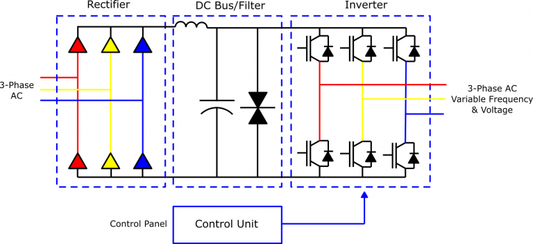
The control unit includes an embedded microprocessor. The onboard microprocessor enables the VFD to perform simple motion functions for single-axis applications or even master-slave architectures. But more sophisticated VFD operations for motion control require a dedicated motion controller or a Programmable Logic Controller (PLC). Note, VFDs used in motion control applications also incorporate high-speed Input/Output ports for feedback, and built-in network connectivity through EtherNet/IP, MODBUS, or CC-Link industrial networks.
In a PWM-based VFD(shown above), three-phase AC power flows through a simple diode bridge rectifier containing six input diodes, which convert it into a fixed voltage DC pseudo–with frequency-dependent AC ripples. The rectified DC power is then cleaned and smoothened by the capacitors in the DC Bus. Next, the array of Insulated Gate Bipolar Transistors (IGBTs) in the Inverter section applies pulse-width modulation to the steady DC voltage from the DC bus capacitors. These IGBTs open and close rapidly thereby generating pulses. If the width of the resulting output pulses can be varied in the output-voltage waveform, then a simulated AC sine wave can be created. Also, the current waveform will be sinusoidal because the AC motor connected to the VFD output is inductive.
Note: Even though the output-voltage waveform from the inverter section comprises square waves due to DC pulsing, these voltage square waves are combined to synthesize an AC signal of the desired frequency. The synthesized AC signal is then fed to the connected AC induction motor. Thus, using the PWM technique VFDs can adjust the speed and output torque of the connected AC induction motor to match the load demands.
In addition, users can configure VFDs for different applications, with settings applied for supply voltage, current, and other parameters so that the VFD operation is suitable for the connected motor and driven load. This helps in optimizing power consumption (avoiding energy wastage), reducing wear and tear, as well as prolonging the service life of the target motor.
VFD Motor-Control Methods
These control methods determine how VFDs control the speed of AC induction motors. They are broadly classified into two categories: (i) Scalar control methods; (ii) Vector control methods. A VFD can thus regulate the speed of the connected AC motor by using one of the two control schemes–Scalar control or Vector control–to vary the input frequency of the AC voltage supplied to that motor. Vector motor-control methods for VFDs are generally more complex compared to scalar control methods, but in some VFD applications, the latter offers significant benefits over the scalar control methods.
The two VFD control methods (Scalar and Vector control) for controlling AC induction motors connected to VFDs are further subdivided into four primary types, namely:(i) Volts-per-Hertz(V/f or V/Hz); (ii) V/Hz with Encoder;(iii) Open-Loop Vector; (iv)Closed-Loop Vector.
These four control schemes rely on a PWM output-voltage waveform to control the target motor. As discussed earlier, Pulse-Width Modulation (PWM) is a method that varies the width of a fixed voltage DC signal by modulating pulse durations to generate a variable AC signal that’s fed to the connected AC motor. The difference between the various motor-control methods used with VFDs lies in how they calculate the voltage requirements of the connected motor at any given moment.
Scalar Motor-Control Methods
Often referred to as V/f or V/Hz control, scalar motor-control methods for VFDs function by optimizing the flux of the connected motor and ensuring that the strength of its electromagnetic field is kept constant, consequently maintaining a constant output torque production. These methods vary both the frequency (f) and voltage (V) of the input power supplied to the target motor, so as to maintain a fixed, constant ratio between the two parameters(V and f). In doing so, the strength of the electromagnetic field is kept constant regardless of motor speed.
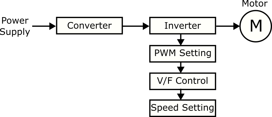
The appropriate voltage to frequency ratio (V/Hz) is equal to the rated voltage of the target motor divided by the motor’s rated frequency. V/Hz control scheme in VFDs is typically implemented as open-loop V/Hz control–without feedback, although closed-loop V/Hz control–with motor feedback–is also implemented in some VFDs. The block diagram to the right illustrates a typical configuration of open-loop V/Hz control:
Vector Motor-Control Methods
Vector control for VFDs, also known as Field Oriented Control (FOC), controls the torque or speed of an AC induction motor by regulating the space vectors of stator current, in a manner comparable to DC control methods but more complicated. This control scheme utilizes complex mathematics to convert a three-phase power system that’s dependent on speed and time to a two-coordinate system (d and q) that’s time-invariant; the stator current in an AC motor consists of two components: the torque-producing element (q) and the magnetizing element (d) of the current.
Like scalar motor-control methods, vector control methods for VFDs can be implemented as closed-loop control or open-loop control. Open-Loop Vector (OLV) control, commonly known as Sensorless Vector Control (SVC), applies a mathematical model of the operating parameters for the target AC motor, instead of using a physical sensing device for feedback. The VFD controller monitors the current and voltage from the connected motor and compares the actual values to the mathematical model. In case of any errors, the controller will correct them by adjusting the voltage and current being supplied to the motor, which in turn adjusts the motor speed and output torque accordingly. Thus, with the SVC method an accurate mathematical model is required, and the VFD control unit must be tuned for proper motor operation.
VFD Control Schemes Using Encoders
In the context of this article, whether a VFD will have an encoder or not depends on the type of motor-control method being used with that VFD. With open-loop motor-control methods like V/Hz and Sensorless Vector Control, the VFD constantly outputs power to the connected AC motor, but it has no means to actually determine if the motor is operating correctly.
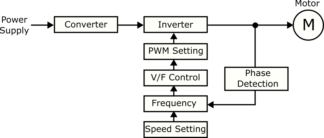
On the other hand, closed-loop scalar and vector motor-control methods incorporate an encoder. By adding an encoder to the target motor as a feedback mechanism for speed detection and providing that feedback to the VFD, the VFD controller can tell the precise speed at which the motor is running. The evaluation between the command speed signal and actual motor speed by the encoder can then be integrated into the VFD’s closed-loop control algorithm to precisely control the motor speed and output torque.
There are two VFD control schemes that incorporate an encoder; so a VFD controlling a motor using any of these two control modes will have an encoder for providing motor shaft feedback. They include:
A) V/Hz Control with Encoder
An encoder can be added to the V/Hz control scheme if the VFD application requires more precise motor speed regulation, along with the need to operate at a higher reference frequency. The encoder feedback enhances V/Hz speed regulation, with speed accuracy at + or – 0.03% of the maximum frequency. While the output voltage of the VFD is still determined by the specific V/Hz pattern programmed by the user into the VFD. This allows for high-speed motor control in the absence of high dynamic responses because frequency and voltage are preset. Speed control range, speed response, and starting torque of closed-loop V/Hz control are all identical to those of open-loop V/Hz control.
However, implementing the closed-loop V/Hz control method can be expensive due to the additional costs of an encoder and a PG card (encoder feedback card). Also, higher VFD operating frequencies are limited by the resolution or PPR (pulses-per-revolutions) of the selected encoder.
B) Closed-Loop Vector Control
Similar to Open-Loop Vector (OLV) control, Closed-Loop Vector (CLV) control scheme utilizes a vector algorithm to determine the VFD output voltage to the connected motor. The key difference between the two is that closed-loop vector control incorporates an encoder while OLV does not. The encoder provides speed/position feedback of the motor shaft, which is sent to the VFD current or speed controller to adjust the supplied voltage and associated frequency to increase/decrease the speed and torque output of the connected motor accordingly.
A VFD-based motor controller using closed-loop vector control with encoder feedback can provide the following:
- 200 percent (%) of the motor’s rated torque as starting torque at 0(zero) rpm. This feature is ideal for VFD applications that require holding a load at standstill (without any movement), such as in elevators, hoists, and cranes.
- High-speed responses of over 50 Hz
- High motor speed control ranges of 1:1500
- Zero speed operation
In addition to being the highest performing motor-control method for VFDs, closed-loop vector control also enables a VFD to run the connected motor in torque-control mode. Torque-control mode allows for the Variable Frequency Drive to directly regulate motor torque output rather than motor speed. This is necessary for any VFD application where torque control takes priority over speed control like in winders, capping, reminders, and web applications. The only shortcoming with this motor-control method is that an encoder must be interfaced with the VFD, and the VFD controller has to be auto-tuned for optimal performance.
Types of Encoders used with VFDs
Motor encoders are interfaced with VFDs for accurate speed or position detection. An encoder for VFD applications is basically an electro-mechanical sensing device connected to the motor shaft and is usually mounted on the rear side of the motor casing. As the motor shaft rotates it generates a series of electrical PPR (pulses per revolution), which are then relayed back to the VFD controller and used as a speed feedback signal.
Most Variable Frequency Drives use encorderless (sensorless) speed control methods. This means that the rotational speed and position (if required) of the motor shaft speed are calculated from the motor’s mathematical model inside the VFD controller. In such cases, the motor mathematical model is computed in real time with the sampling time ranging in microseconds. Hence, a feedback mechanism for the detection of motor speed/position is not required; so it’s not necessary to install an encoder on the motor shaft.
However, computational algorithms for the motor’s mathematical model have their limits. The computation is generally less accurate at very low motor speeds. It’s normally sufficient only for a short acceleration throughout a constant range. Thus, manufacturers recommend the use of a speed encoder if the VFD is required to run the motor continuously at a very low speed.
Encoderless motor-control methods used with VFDs are usually preferred in general purpose VFD applications. But some applications require the VFD to be interfaced with a speed encoder. Such applications are characterized by:
- Motor drives requiring high speed accuracy
- Motor drives with highly dynamic and wide speed ranges
- Applications requiring high starting torque at very low speed or at a standstill
- VFDs needed to catch a spinning AC motor (fast flying start)
The VFD manufacturer shall advise if a speed encoder will be required for the intended VFD application or not.
Besides speed encoders, some VFD applications may also require a position encoder. These are applications involving synchronous motor drives requiring precise control and with high dynamics or synchronous machines where using encoderless control to determine motor shaft position is challenging.
The two most common types of encoders interfaced with VFDs include:
Incremental Encoder: Also known as a pulse encoder, this encoder is used as a feedback mechanism for motor speed detection. It counts the number of pulses per revolution, mainly on optical principle, and calculates the motor speed. There are many types of incremental speed encoders available on the market; hence, be sure to select a speed encoder that is compatible with your VFD (check compatibility in terms of the format of the output signal) and whose resolution (PPR) will suffice your application needs.
Absolute Encoder: This is mainly used as a position encoder to determine the absolute position of the rotor shaft. But depending on the VFD used, an absolute encoder can also provide a speed signal that’s derived from the rotor position. Thus, with an absolute encoder, you won’t necessarily need two different types of encoders for speed and position signals.
Key Takeaways
- A VFD regulates the speed of an AC induction motor by converting the fixed frequency, fixed AC voltage being supplied to the motor into a variable AC frequency and voltage.
- Different VFD designs presently available on the market use a variety of techniques to adjust the input frequency and associated voltage to an AC motor. The most commonly used and most effective technique is Pulse-Width Modulation (PWM).
- A PWM-based VFD consists of four basic components: (i) Rectifier unit for converting AC signal into DC signal. (ii) DC Bus for cleaning the rectified DC voltage. (iii) Inverter section for converting the filtered DC voltage to AC voltage; PWM frequency modulation is applied in this section. (iv) Control unit for regulating the switching speed of the power transistors i.e. IGBTs or MOSFETs in the inverter unit.
- VFDs control the speed of AC induction motors using two types of motor-control methods, namely: (i) Scalar control methods; (ii) Vector control methods.
- The two motor-control methods (Scalar and Vector control) are further subdivided into four primary types: (i) Volts-per-Hertz (V/f or V/Hz); (ii) V/Hz with Encoder; (iii) Open-Loop Vector; (iv) Closed-Loop Vector.
- The four control schemes rely on a PWM output-voltage waveform to control the target AC motor.
- Both scalar and vector control methods for controlling AC induction motors connected to VFDs can be implemented as open-loop or closed-loop.
- Open-loop control methods don’t incorporate a feedback mechanism for motor feedback. They include (i) V/Hz control; (ii) Sensorless Vector Control or Open-Loop Vector (OLV) control.
- Closed-loop control methods use encoders for motor feedback. They include: (i) V/Hz Control with Encoder; (ii) Closed-Loop Vector (CLV) Control.
- VFDs controlling AC induction motors using either Closed-Loop V/Hz control (V/Hz control with encoder) or Closed-Loop Vector (CLV) control have encoders for motor feedback.
- VFD manufacturers will state the motor-control methods of the selected drive technology and whether a speed or position encoder will be required for the intended VFD application.
- The two types of encoders commonly interfaced with VFDs are Incremental and Absolute Encoders. But most motor drive applications require the VFD to be interfaced with a speed encoder.
DO Supply Inc. makes no representations as to the completeness, validity, correctness, suitability, or accuracy of any information on this website and will not be liable for any delays, omissions, or errors in this information or any losses, injuries, or damages arising from its display or use. All the information on this website is provided on an "as-is" basis. It is the reader's responsibility to verify their own facts.