Ladder Logic Essentials: A Beginner’s Guide to PLC Programming
Imagine stepping into a factory with machines seamlessly working, conveyor belts smoothly transitioning, and indicator lights rhythmically flashing. This synchronized operation has a central orchestrator, the Programmable Logic Controller (PLC). But how do these machines receive instructions on what tasks to perform? That’s where Ladder Logic steps in.
Originating from simple diagrams that resemble ladders, Ladder Logic translates our commands into actions that the PLC can understand. Think of it as a visual storyboard for machinery, where each segment or ‘rung’ provides a specific directive.
Approaching Ladder Logic might appear challenging at first. However, with some guidance and understanding, it becomes as straightforward as learning the rules of a new board game. This article aims to demystify the basics, offer insightful tips, and ensure that by the end, the world of PLC programming feels less like a puzzle and more like another tool accessible to you.
Basics of Ladder Logic
Just like any programming software, reading its rules, its jargon, and understanding the core principles of the language is important before taking the first steps forward.
Symbolism:
At the core of Ladder Logic are symbols that represent different components or
actions. Here’s a quick breakdown:
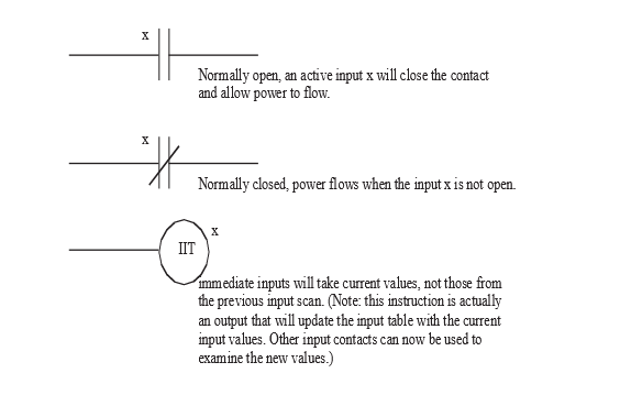
- Contacts:
Think of them as gatekeepers. There are two primary types:
- Normally Open (NO): A gate that’s typically open but closes under certain conditions.
- Normally Closed (NC): A gate that’s generally closed, opening only when specific conditions are met.
- Coils (Relays): If contacts are gatekeepers, then coils are the decision-makers, signaling actions or responses based on the conditions set by the contacts.
Power Flow:
Just like water flows in a river, Ladder Logic has a directional flow. In most
cases, this flow is from left to right, similar to how many of us read. On the
left, you have the power rail (often represented as a vertical line) and the
return path on the right. The logic or instructions are laid out in between,
like rungs on a ladder.
Organizing the Workspace:
The beauty of Ladder Logic lies in its clarity. Each horizontal line or ‘rung’
represents a separate instruction or logic sequence. Think of each rung as a
sentence in a story – by stringing these sentences together, a complete
narrative (or, in this case, a program) is formed.
Basic Structure:
Each rung in Ladder Logic starts with an input (or condition) and ends with an
output (or action). In between, you can have various conditions and operators,
guiding the flow and determining whether the final action gets executed.
As with any new skill or game, practice is the key. The more familiar one becomes with these symbols and their interactions, the more intuitive creating and reading Ladder Logic becomes.
Setting Up Your First Ladder Logic Diagram
Starting the process of creating the initial Ladder Logic diagram can be like creating a mind map. At first, the canvas is empty, but as you add symbols and connections, it begins to take shape and tell a story. These are often referred to as flow charts and can be extremely helpful when programming in general. The rule is to spend 80% of the time planning what you want to do and 20% of the time actually writing the program.
Choose the Right Software:
Before even drawing the first rung, it’s essential to have the right tools.
There are many PLC programming software options available, both proprietary and
open-source. Some popular choices include Allen-Bradley’s RSLogix, Siemens’ TIA
Portal, and CODESYS. Select one that’s compatible with the PLC being used and
feels comfortable to navigate.
Understand the Objective:
What task should the PLC perform? Maybe it’s to start a motor when a button is
pressed or sound an alarm when the temperature rises too high. Clearly defining
the objective will provide direction for the diagram.
Start Simple:
Begin with a basic rung. Place an input on the left (like a switch or sensor)
and an output on the right (like a motor or light). This straightforward rung
would mean: “If this input is activated, then trigger this output.”
Add Conditions:
As familiarity grows, it’s possible to introduce more conditions. Using the
Normally Open and Normally Closed contacts can allow for more nuanced
instructions, such as: “If this button is pressed AND this other sensor is
not activated, turn on the light.”
Test and Refine:
Once the diagram is set up, testing it, either through software simulation or
on a real PLC, is crucial if it’s safe and feasible. This step will highlight
areas that might not work as expected, providing opportunities to refine and
improve the logic.
Keep It Neat and Documented:
As the diagram grows, organization becomes key. Make sure rungs are well-spaced
and clearly labeled. This not only aids in personal understanding but ensures
that anyone else reviewing the diagram can follow the logic effortlessly.
Drafting the first Ladder Logic diagram is an achievement in itself. However, like any masterpiece, it might need a few brush strokes and adjustments before it’s perfect. As experience accumulates, the process will feel more intuitive, and the canvas will come to life much quicker.
Key Elements in Ladder Logic
Beyond the foundational concepts, Ladder Logic has various versatile elements that bring depth and complexity to the diagrams. Just as a painter uses different brushes and colors, understanding these components allows for a richer and more nuanced PLC programming experience.
Inputs/Outputs (I/O):
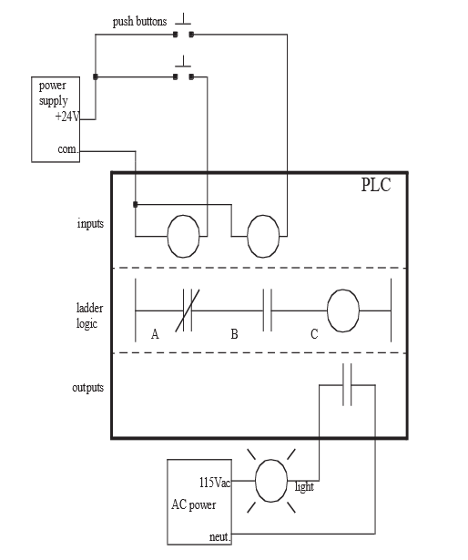
- Inputs: These are signals or data received by the PLC. Common inputs include buttons, switches, and sensors that can detect conditions such as temperature, pressure, or proximity.
- Outputs: After processing the inputs based on the programmed logic, the PLC sends signals to outputs. Outputs can be motors, valves, lights, or other devices performing actions.
Internal Relays:
- These are virtual relays within the PLC software and don’t have a physical presence. They serve as intermediary steps in logic sequences or store temporary conditions, making them indispensable for more complex operations.
Timers and Counters:
- Timers: As the name suggests, timers introduce delays or measure time intervals. They can be configured to start or stop devices after a specified duration.
- Counters: These tally the number of times a specific event occurs. For instance, they can count how many times a button is pressed or a sensor is activated.
Arithmetic and Comparison Instructions:
- Arithmetic Instructions: These are operations like addition, subtraction, multiplication, and division. They are essential when working with variables, such as calculating averages or converting units.
- Comparison Instructions: They allow for conditions like “greater than,” “less than,” or “equal to.” For instance, if one wishes to compare the value of a temperature sensor to a set threshold and make a decision based on that.
Special Functions:
Different PLC brands and models offer unique functions
specific to their hardware and software capabilities. These can range from
advanced mathematical functions to specialized communication protocols.
Each of these elements, when employed correctly, can immensely enhance the versatility and capability of a Ladder Logic program. It’s like constructing a sentence; while knowing nouns and verbs is crucial, adding adjectives, adverbs, and punctuation can enrich the narrative. Similarly, as one becomes more adept with these key elements, the PLC programs crafted will be more dynamic and efficient.
Best Practices in Designing Ladder Logic
Creating an effective Ladder Logic program goes beyond just understanding the key elements; it’s also about crafting diagrams that are efficient, maintainable, and easily understood by others. Below are some of the best practices to keep in mind:
Start with a Plan:
Before jumping into the software, sketch out the process flow or the logic
sequence on paper or a digital tool. Having a blueprint can streamline the
actual programming stage.
Keep It Modular:
Instead of designing one long and complex sequence, break down the logic into
smaller, manageable modules or sections. This modular approach can aid in
troubleshooting, updating, and enhancing readability.
Prioritize Safety:
Safety should be at the forefront of any Ladder Logic design. Always include
provisions for emergency stops, alarms, or safe defaults to prevent potential
hazards.
Use Consistent Naming Conventions:
While most PLC software will allow users to name variables or I/O points, following
a consistent naming convention is vital. For instance, using
“Temp_Sensor1” instead of vague names like “TS1” can make a
big difference in clarity.
Avoid Overcomplicating:
While showing off complex logic prowess might be tempting, always opt for
simplicity where possible. A straightforward and clean logic sequence is
usually more reliable and easier to understand than a convoluted one.
Comment Generously:
Most PLC programming platforms allow for comments to be added next to rungs or
elements. These comments can be invaluable, especially when returning to a
project after some time or when sharing it with others.
Regularly Test and Debug:
Instead of waiting until the end to test the entire logic, adopt an iterative
approach. Test and debug each module or section individually before integrating
them. This method can save time and reduce potential errors.
Stay Updated and Seek Feedback:
Ladder Logic, like any other discipline, evolves over time. Stay updated with
the latest trends, tools, and techniques. Furthermore, sharing diagrams with
peers or mentors and seeking feedback can offer fresh perspectives and
insights.
Crafting a Ladder Logic diagram is not just about connecting symbols; it’s the art of translating a real-world process into a digital format. By adhering to these best practices, one can ensure that their PLC programs are not just functional but also efficient, safe, and easily comprehensible.
Simulation and Testing
After designing a Ladder Logic program, it’s imperative to ensure that it functions as intended. Enter simulation and testing: the stage where theory meets practice. This phase determines if the designed logic meets its objectives and identifies potential issues that might arise in a real-world scenario.
The Role of Software Simulators:
PLC software often comes equipped with simulators that emulate how the PLC
would respond to the given logic without the need for physical hardware. It
provides a safe environment to:
- Monitor how inputs and outputs respond.
- Identify and troubleshoot any logical errors.
- Observe the sequence of operations under various conditions.
Hardware Testing:
Once the logic performs satisfactorily in a simulated environment, it’s time
for hardware testing:
- Use a controlled environment, ensuring all safety measures are in place.
- Observe how actual devices, be they sensors, motors, or relays, respond to the logic.
- Monitor system behavior under different scenarios, including boundary and extreme conditions.
Iterative Testing:
- Start with individual modules or rungs, testing each segment separately.
- Gradually combine these modules, continuing to test at every integration point. This modular approach ensures errors are detected at an early stage and simplifies the troubleshooting process.
Document Observations:
- Maintain a record of all observations, both expected and unexpected.
- Note down any discrepancies, unexpected behaviors, and areas of improvement.
- This documentation aids in refining the logic and serves as a valuable reference for future projects.
Validation:
Ensure that the final behavior aligns with the objectives set at the beginning.
Validating the logic against real-world requirements guarantees that the
solution meets the desired criteria and standards.
Continual Monitoring:
After deployment, keep an eye on the PLC system as it operates:
- Use built-in diagnostics and monitoring tools.
- Periodic checks can help detect wear and tear or potential issues before they escalate.
Simulation and testing are not mere checkpoints but integral parts of the Ladder Logic development process. They bridge the gap between design and real-world application, ensuring that the final solution is not only functional but also reliable and safe. As the journey continues, understanding real-life applications and case studies can offer invaluable insights into the dynamic world of Ladder Logic.
Advancing Your Skills
Mastering the basics of Ladder Logic is just the beginning. As with many disciplines, there’s always room for growth, refinement, and specialization. Here are some ways to continue on the path of expertise:
Dive Deeper into Advanced Functions:
Beyond basic relays, timers, and counters, explore the deeper functionalities
and specialized instructions offered by different PLC brands. Each PLC often
comes with a unique set of advanced features tailored to specific industry
needs or applications.
Engage in Continuous Learning:
- Attend workshops, webinars, and seminars related to PLCs and automation.
- Enroll in specialized courses or certifications. Many institutions offer advanced PLC programming courses that delve into intricate topics and applications.
Join Online Communities:
There are countless forums, groups, and online communities dedicated to PLC
programming and Ladder Logic:
- Engage in discussions, share personal projects, and seek advice from seasoned professionals.
- Collaborative problem-solving can provide fresh perspectives and introduce novel solutions.
Experiment with Different PLC Brands:
While the fundamental principles of Ladder Logic remain consistent, each PLC
brand has its nuances. By familiarizing oneself with different software and
hardware platforms, versatility and adaptability in the field increases.
Undertake Real-World Projects:
Nothing beats hands-on experience:
- Volunteer or take on projects that require PLC programming, even if they are outside the usual scope or comfort zone.
- These challenges can sharpen skills, introduce real-world constraints, and deepen understanding.
Stay Updated with Industry Trends:
The world of industrial automation is ever evolving:
- Keep an eye on the latest technologies, methodologies, and best practices.
- Embracing new trends early can offer a competitive edge and open doors to specialized niches.
Mentor and Teach:
Imparting knowledge can be one of the best ways to solidify one’s
understanding:
- Offer guidance to newcomers in the field.
- Consider conducting workshops or creating online content, sharing experiences and insights.
Climbing the ladder (pun intended) of expertise in Ladder Logic requires dedication, continuous learning, and hands-on application. As the journey progresses, it’s not just about mastering the technique but also about innovating, sharing, and shaping the future of industrial automation. As one advances, the horizon broadens, revealing a world rich in opportunities and challenges, all awaiting exploration.
Final Thoughts
Ladder Logic might sound a bit technical at first, but it’s really about using simple drawings to tell machines what to do. Think of it like giving step-by-step instructions to a friend on how to make a sandwich, just like how each step matters in making that perfect sandwich, in Ladder Logic, every line and symbol has its purpose.
Starting with the basics, anyone can learn how to put together these instructions. And as they practice more, they’ll discover there’s a lot more they can do. It’s similar to how some people move from making simple sandwiches to creating gourmet meals.
The key is not to get discouraged. Every bit of learning, every little experiment, adds up. And soon, those simple drawings can lead to some really cool stuff in the real world, like making machines work in factories or controlling lighting in big stadiums.
So, for anyone diving into Ladder Logic, it’s an exciting journey. It’s about learning, creating, and watching those creations come to life. And who knows? With some time and experience, anyone might just become the go-to person for solving tricky problems or coming up with new ideas.
DO Supply Inc. makes no representations as to the completeness, validity, correctness, suitability, or accuracy of any information on this website and will not be liable for any delays, omissions, or errors in this information or any losses, injuries, or damages arising from its display or use. All the information on this website is provided on an "as-is" basis. It is the reader's responsibility to verify their own facts.