PowerFlex 525 Fault Codes: What They Mean and How to Fix Them
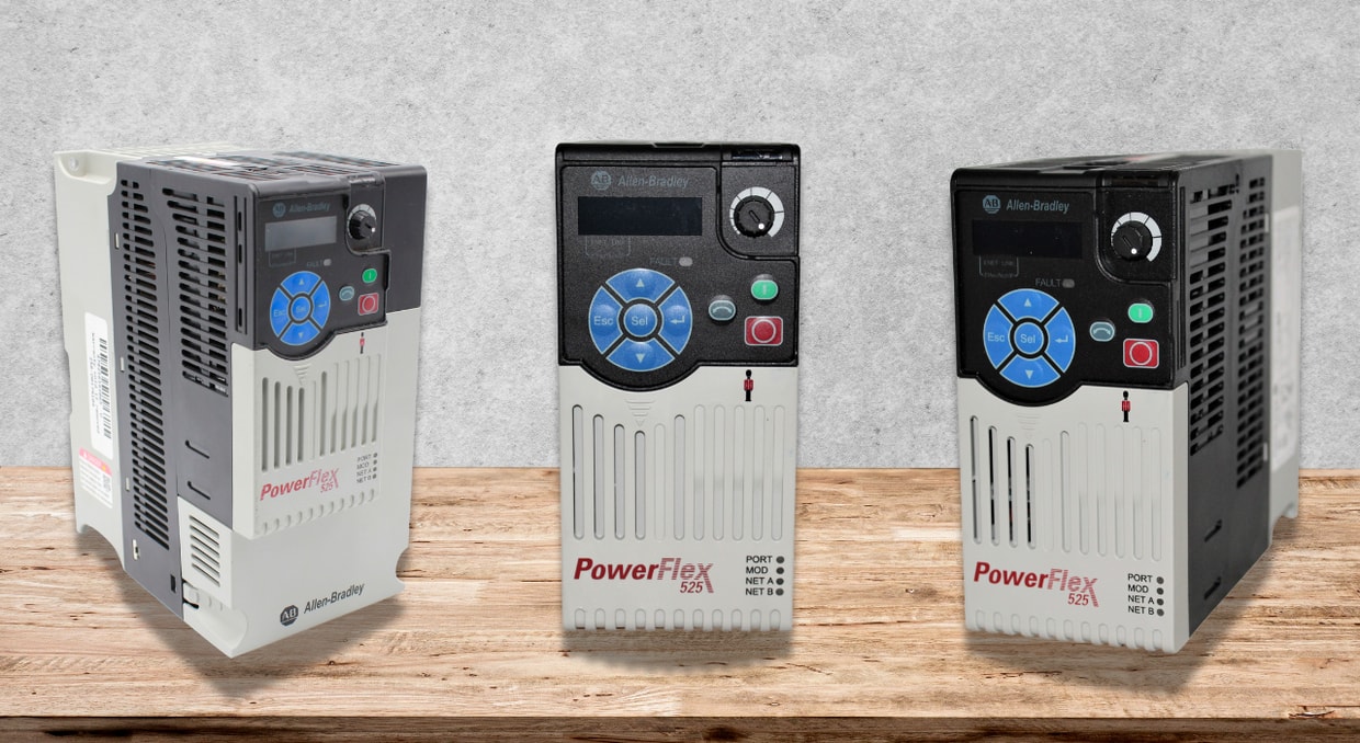
The PowerFlex 525 drive is a dependable workhorse found in many control panels worldwide. It keeps motors moving at the right speed, delivers the torque that you expect, and plays nicely with Allen-Bradley PLCs or just about any SCADA system you have. Though, like any other VFD, it can be temperamental at times. Though when that happens, it does so through a well-thought-out fault and diagnostic system.
Understanding what these faults mean and what to do about them turns occasional alarms from stressful surprises to quick fixes. Today, we are here to help walk you through what the more common faults really mean and how to get your drive back on track.
Fault & Diagnostic Framework of PowerFlex 525
First of all, let’s discuss the diagnostic framework of the drive series and how it identifies the problem using specific PowerFlex 525 Fault Codes.
• The drive maintains a fault history buffer for up to 10 past faults. The three most recent fault codes are usually grouped and can be read via parameters or messaging.
• PowerFlex 525 Fault Codes are typically shown on the drive’s display, or can be retrieved via communication (e.g., via a MSG instruction or over EtherNet/IP).
• Some faults are auto-recoverable (auto-restartable) depending on configuration (for instance, based on parameter A541: Auto Rstrt Tries).
• Others require manual clearing or intervention.
• PowerFlex 525 Fault Codes often reference drive parameters (e.g. A484, A530, A557) that influence behavior like acceleration time, current limits, safety input configurations, etc.
Because there are many fault codes in PF525 (some sources list 30+), we will focus on the most frequently encountered ones, describing how to interpret them and respond.
Fault Codes for Powerflex 525
Below is a summarized table of different fault codes.
| Code | Name of the fault | What it means | Causes of the fault | Possible solution |
| F000 | No Fault | No fault currently present | — | — |
| F002 | Auxiliary Input | An auxiliary external trip input was triggered | External wiring error, unintended signal, control logic issue | Check remote wiring, input wiring, and control logic to intentionally trip. |
| F003 | Power Loss | Single-phase operation detected or loss of power to one phase under load | Blown fuse, phase loss on supply, weak supply, noisy voltage | Monitor AC supply, check fuses, and ensure all input phases are present. |
| F004 | UnderVoltage | The DC bus voltage dropped below the minimum threshold | Low input voltage, sagging supply, heavy load | Monitor input AC, check supply line stability. |
| F005 | OverVoltage | DC bus voltage exceeded the maximum allowed threshold | Regeneration from the motor (braking), line voltage surges, and decelerating too fast | Extend deceleration time, enable dynamic brake, and check voltage transients. |
| F006 | Motor Stalled | The drive cannot accelerate or decelerate the motor | Mechanical load too heavy, ramp settings too aggressive, motor jammed | Reduce load, adjust acceleration/deceleration times (P041, A442, etc.), and check current limit settings. |
| F009 | Control Card OverTemp (CC OvrTmp) | The control module temperature is too high | Poor ventilation, overheated environment, blocked airflow | Check airflow, remove obstructions, and inspect for debris/grime. |
| F012 | Hardware Overcurrent | Output current exceeded hardware limit | Excess load, short, bad wiring, too much regenerative load | Check wiring, load, programming, and boost settings. |
| F013 | Ground Fault | A current path to earth ground is detected in one or more output terminals. | Motor winding insulation failure, wiring insulation fault, stray ground on cable | Inspect motor and cable insulation; isolate the suspect phase; check for ground leakage. |
| F015 | Load Loss | The output torque current dropped below a threshold while the drive is running. | Load disconnection, broken coupling, and mechanical slipping | Check coupling, verify load presence, and inspect input/output mechanicals. |
| F021 | Output Phase Loss | Phase loss in output if enabled | Motor wiring fault, broken motor phase, incorrect wiring | Verify motor wiring, check phase continuity. |
| F029 | Analog Input Loss | Loss of analog input signal (voltage or mA) when configured to fault on loss | Open circuit in analog wiring, loose connector, or failure in the sensor | Check wiring, connectors, and analog input devices. |
| F033 | Auto Restart Tries | Drive attempted to auto-restart a fault more times than allowed (by parameter A541) | Persistent fault not cleared, auto-restart limit reached | Fix the root cause fault, then manually clear or disable auto-restart. |
| F048 | Params Defaulted | Drive wrote default values to EEPROM (parameters reset) | Configuration reset event (power glitch, firmware issue) | Reprogram the parameters, check integrity, and power-cycle the drive. |
| F059 | Safety Open | The safety inputs (S1, S2) are not enabled or missing | Safety circuit not wired or miswired, missing jumpers | Verify safety wiring; check S+, S1, S2 connections, or jumper if safety is not used. |
| F063 | Software Overcurrent | Exceeded the software’s current limit over time | Prolonged overload, programming issues | Reduce load, check torque settings, and adjust current limit/time settings. |
| F070 | Power Unit Fault | Failure in the drive’s power circuitry | Internal hardware failure | Cycle power, if it persists, replace the drive power module. |
| F071 / F072 / F073 | Net Loss / Comm Loss | Communications (DSI / option / Ethernet) lost | Cable failure, improper settings, network issue | Check communication cabling, network health, and configuration. |
| F080 | Autotune Failure | Autotune process failed or was cancelled | Motor wiring issue, incorrect parameters, load present | Re-run autotune, verify motor wiring, and remove load during autotune. |
| F091 | Encoder Loss | Loss of encoder feedback signal (in positioning mode) | Wiring, encoder fault, signal break | Check encoder wiring, replace or repair the encoder. |
| F094 | Function Loss | A “function loss” or “freeze-fire” input configured is inactive | Fault or open function input | Re-apply required input, cycle power. |
| F114 | uC (Microcontroller) Failure | Microprocessor failure or internal fault | Electrical stress, EMI/noise, firmware corruption | Power-cycle the drive, check grounding/EMI, and consider a firmware upgrade or module replacement. |
| F122 | I/O Board Failure | Failure detected in the control & I/O section | Faulty I/O module | Replace the control module or the I/O board. |
| F125 | Flash Update Required | Firmware mismatch or corruption | Needs firmware reflash | Perform a firmware upgrade with the correct file. |
Notes / Tips
Some faults (marked in the manual) may be cleared by auto-restart, while others ignore auto-restart settings.
- Always refer to the 520-DU001 (PowerFlex 525 manual) for the complete PowerFlex 525 Fault Codes listing and parameter definitions.
- Use the drive’s display, front panel navigation (F-parameters), or connect via software tools (Connected Components Workbench, etc.) to interrogate fault codes.
Fault History, Logging & Diagnostics
To make effective use of PowerFlex 525 Fault Codes, consider how to retrieve and use fault history and diagnostics:
- Fault History Buffer: The PF525 stores up to 10 past fault codes. The most recent three can often be retrieved via front panel parameters F604 to F610 or through B007/B008/B009 registers.
- Communication-Based Readout: Using MSG (e.g., Class 0x97, Instances 1–3, Attribute 2), you can request the fault description strings.
- Tag Mapping / HMIs: Many installations map fault code integers to human-readable descriptions on the HMI or SCADA. Some forums mention storing a fault lookup table or dataset to translate codes to text.
Protective Measures for Mitigation
Described below are some preventive measures to address faults in the drive:
Solid Grounding & Shielding
- Ensure motor cable shields are well-terminated.
- Use single-point grounding, avoid ground loops.
- In cases of F114 or intermittent faults, many users grounded C1/C2 to GND to reduce noise.
Parameter Tuning & Limits
- Don’t run the motor too close to limits. Keep margins on current, torque, and acceleration.
- If regenerative loads are common (e.g., stopping big inertial loads), use dynamic braking or extended deceleration.
- Use auto-restart judiciously; automatic recovery can mask real problems.
Ventilation is a Must
- Ensure fans are operational and air flow is adequate.
- Avoid ambient temperature beyond ratings.
Wiring & Cable Quality
- Use appropriate gauge, insulation, and length for motor and power wiring.
- Minimize voltage drops and ensure phase balance.
- Routinely inspect for wear, insulation damage, or connector issues.
Firmware & Software Updates
- Keep firmware up to date (using manufacturer-provided updates) to address known bugs or improvements.
- Use recommended communication settings (e.g., avoid excessive network traffic or switch settings).
- In field cases, firmware changes resolved F114 issues.
Isolate Mechanical Issues
- Always eliminate mechanical binding, misalignment, coupling slippage, load over-sizing, or intermittent load swings.
- Vibration, loose parts, or momentary torque overloads often cause “fault ripple.”
Diagnostics & Logging
- Log fault occurrences with timestamp, operating conditions, load, speed, etc.
- Use trend analysis to detect creeping issues (e.g., gradually worsening insulation, heating, wear).
- On repeated faults, disable auto-restart to capture the “real” fault event.
Safe and Systematic Clearing
- After fixing the cause, clear the fault using drive reset (or manually via the front panel).
- Do not power-cycle continuously without root cause repair, as that can stress drive components.
Final Thoughts
In conclusion, you need to have an understanding of the PowerFlex 525 Fault Codes; only then will you be able to comprehend the issues and their solutions.
You have to simply start by:
- Reading and mapping the fault code
- Checking associated drive parameters
- Investigating the mechanical and electrical side causes
- Logging historical data
- Applying firmware or configuration corrections
So, as a whole, by combining an understanding of various fault codes, inspecting them correctly, and taking appropriate actions, you can increase the drive’s efficiency.
If this doesn’t work, we at DO Supply offer a repair service for broken or malfunctioning automation equipment. What you get back is working equipment, exceptional service, and a 2-year warranty for added peace of mind. If that sounds like something you need, give us a call or send us an email today, and we would be more than happy to help you however we can. We also made a blog about the most common Allen-Bradley drive failures and how to prevent them here. As always, thank you for reading!
DO Supply Inc. makes no representations as to the completeness, validity, correctness, suitability, or accuracy of any information on this website and will not be liable for any delays, omissions, or errors in this information or any losses, injuries, or damages arising from its display or use. All the information on this website is provided on an "as-is" basis. It is the reader's responsibility to verify their own facts.