PLC Communication Delays and Their Real Impact
Industrial automation systems depend on PLCs exchanging data reliably and on time. When communication delays enter that chain, whether between PLCs and an HMI, between controllers on a network, or between PLCs and field devices, the consequences extend well beyond a sluggish screen update. In process-critical environments, even a few milliseconds of unexpected latency can cascade into equipment damage, unsafe states, or production loss.
What Causes Communication Delays in PLC Systems?
Delays in PLCs communication originate from multiple layers of the system. At the physical layer, cable quality, termination integrity, and media type set the baseline. At the network layer, excessive node counts, improper topology, and bandwidth saturation introduce queuing delays. At the application layer, message scheduling, packet fragmentation, and polling intervals determine how frequently data is actually refreshed.
In EtherNet/IP-based systems, the dominant protocol on Allen-Bradley ControlLogix and CompactLogix platforms, the primary messaging mechanisms are Implicit Messaging (Class 1, cyclic I/O) and Explicit Messaging (Class 3, connected or unconnected). Implicit messaging runs on a fixed Requested Packet Interval (RPI), configurable from 1 ms to several seconds. When network congestion causes a packet to arrive outside the RPI window, the controller flags a connection timeout, and the output tag retains its last known state or goes to a configured fault value. This is not a visible alarm; it is a silent state that requires diagnostic polling of the connection object (instance 0x01) to detect.
On PROFIBUS DP networks, the token-passing mechanism assigns each slave a guaranteed time slot per bus cycle. As the node count increases, the bus cycle time increases linearly. A network configured for 12 Mbps with 31 slaves and a target rotation time (Ttr) of 10 ms will degrade to an effective cycle time of 25–30 ms if additional slaves are added beyond the calculated Ttr budget. The GSD file parameters Min_Slave_Interval and Max_Tsdr define the timing boundaries; misconfiguration here is a frequent source of intermittent communication faults that occur only under full-load conditions.
MODBUS RTU, still widely deployed in energy metering and legacy instrumentation, is inherently poll-response with no asynchronous notification. A master polling 20 slaves at 9600 baud with 10-register read requests per slave will require a complete scan cycle exceeding 400 ms, which is inadequate for any control loop requiring sub-100 ms feedback. Increasing the baud rate to 115200 reduces this, but cable runs exceeding 15 meters without proper RS-485 biasing and termination resistors introduce reflection errors that force retries, negating the speed advantage.
RPI Misconfiguration and Its Effect on Control Loop Performance
The Requested Packet Interval is one of the most frequently misconfigured parameters in Ethernet/IP systems. Engineers often set all device RPIs to a default value, commonly 20 ms, without considering the actual control-loop scan rate or the criticality of the data exchanged.
A servo drive axis receiving position feedback over EtherNet/IP with an RPI of 20 ms is operating with a feedback latency that fundamentally limits the achievable closed-loop bandwidth. The Nyquist criterion for digital control systems requires that the sampling rate be at least twice the highest frequency of interest in the process. For a motion control loop targeting a 10 Hz bandwidth, the RPI must be 50 ms or lower. Still, to maintain acceptable phase margin, practical implementations require the RPI to be 5–10 times the loop bandwidth, pushing the requirement to 10–20 ms. At 20 ms RPI, the control loop is already at its boundary; any additional delay due to network congestion reduces phase margin, leading to oscillation or instability.
Conversely, setting RPIs too aggressively, 1 ms across 50+ devices on a single Ethernet/IP network, floods the network with unicast packets. Each Class 1 connection generates a bidirectional packet stream. At 1 ms RPI with 50 devices, the network is processing 100,000 packets per second before any HMI, historian, or explicit message traffic is added. Managed switches with QoS (IEEE 802.1p) prioritization can protect I/O traffic. Still, without it, packet collisions and buffer overflows in unmanaged switches produce exactly the intermittent delays that the aggressive RPI was intended to prevent.
Backplane Latency in Multi-Rack ControlLogix Systems
In ControlLogix systems with multiple racks connected via ControlNet or EtherNet/IP, the I/O data for remote racks does not arrive synchronously with the local backplane scan. The local 1756 backplane operates at approximately 100 Mbps with a scan latency of under 1 ms for modules in the same chassis. Remote I/O across ControlNet introduces scheduled transfer latency equal to the Network Update Time (NUT), configurable from 1 to 100 ms.
When a program references a tag mapped to a remote I/O module, it is reading data that is at least NUT milliseconds old. If the program scan time is 10 ms and the NUT is 10 ms, the actual data age can be as high as 20 ms in the worst case, double what a naive calculation would suggest. For process interlocks based on remote pressure or temperature inputs, this data age must be explicitly accounted for in the hazard analysis. Relying on a remote digital input for a safety interlock without understanding its effective latency is a design error that HAZOP review should catch but frequently does not.
PROFINET IRT and the Real-Time Class Spectrum
PROFINET defines three communication classes with increasing levels of determinism. RT (Real-Time, Class 1) provides cycle times down to 1 ms with jitter under 1 ms, suitable for standard I/O and drive control. IRT (Isochronous Real-Time, Class 3) provides cycle times down to 250 µs with jitter under 1 µs, required for synchronized multi-axis motion control.
The critical distinction is that IRT requires hardware-level scheduling. Standard Ethernet switches, even managed ones, cannot participate in an IRT network because they introduce non-deterministic queuing delay. IRT networks require PROFINET-specific switches or integrated switch ports on IRT-capable devices that implement forwarding based on a pre-calculated schedule generated during network commissioning. If a non-IRT switch is inserted into an IRT network segment, even temporarily during maintenance, the isochronous transfer is broken, and all IRT-dependent axes lose synchronization. Siemens SINAMICS drives in DSC (Dynamic Servo Control) mode will fault with F07900 (setpoint timeout) within two missed IRT cycles.
OPC UA Publish-Subscribe and Latency in SCADA Integration
At the SCADA integration level, OPC UA has become the preferred data exchange standard, but its Publish-Subscribe (Pub/Sub) model introduces latency characteristics that differ from the client-server model it is increasingly replacing. In client-server OPC UA, the client sets a sampling interval and a publishing interval. Data is sampled at the server at the sampling interval, queued, and delivered to the client at the publishing interval. If the publishing interval is 1 second and a process variable change occurs 500 ms after the last publish cycle, the SCADA system will not reflect that change for another 500 ms, a maximum latency of 1 second per change event.
Detecting and Diagnosing Communication Delays
Effective diagnosis of PLCs communication delays requires measurement at multiple system levels rather than inference from symptom observation alone.
At the network level, Wireshark with the EtherNet/IP or PROFINET dissector plugin captures packet timestamps with microsecond resolution. Filtering on the CIP Item ID or PROFINET Frame ID isolates I/O traffic from background traffic. Comparing the inter-packet arrival time against the configured RPI or cycle time directly quantifies jitter. Sustained jitter exceeding 20% of the RPI indicates network congestion or switch buffer overflow.
At the controller level, ControlLogix provides the GSV (Get System Value) instruction to read communication diagnostics from connection objects. Reading attributes 14 (Packet Receive Count) and 15 (Packet Transmit Count) from instance 0x01 of the Message Router object at timed intervals allows calculation of actual packet throughput relative to expected throughput. A discrepancy greater than 5% over a 60-second interval indicates dropped or retransmitted packets.
On PROFIBUS networks, the GSD-based diagnostic byte (byte 0 of the standard diagnostic response) provides station-level communication status. Bit 3 of diagnostic byte 0 (Ext_Diag) set to 1 indicates that extended diagnostics are present, which requires reading subsequent diagnostic bytes to identify the fault type, invalid data, watchdog timeout, or parameter error.
Mitigation Strategies for Communication Delay Reduction
Addressing PLCs’ communication delays requires a layered approach targeting each contributing factor:
Network segmentation using VLANs isolates I/O traffic from HMI, historian, and IT traffic, preventing non-deterministic background traffic from consuming bandwidth allocated to control-critical data. Managed switches with IEEE 802.1p QoS should assign CIP Class 1 (EtherNet/IP I/O) traffic to the highest priority queue.
Local I/O mapping, placing high-speed interlock signals on local chassis I/O rather than remote I/O modules, eliminates network-induced latency for the most time-critical signals. Remote I/O should carry status and monitoring data; hardwired local I/O should carry trip, interlock, and high-speed control signals.
Final Thoughts
In conclusion, PLCs communication delays are not background noise to be tolerated; they are measurable system parameters that directly determine the achievable performance of control loops, the responsiveness of safety systems, and the accuracy of SCADA data. Every communication delay has a source: an overloaded network, a misconfigured RPI, an unsupported switch in an IRT segment, or a MSG queue in saturation. Identifying and quantifying that source requires instrumented measurement, not assumption. When delays are understood and controlled, PLCs deliver the deterministic, reliable performance industrial automation demands.
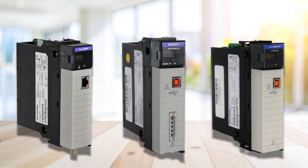
At DO Supply, we carry a wide range of industrial automation components, including Allen-Bradley PLCs, ControlLogix and CompactLogix hardware, communication modules, remote I/O, HMIs, drives, and network related parts to help keep your control systems responsive and reliable. We also offer repair services backed by our two-year warranty to breathe new life into your failing components. Give us a call today to see what we can DO for you!
DO Supply Inc. makes no representations as to the completeness, validity, correctness, suitability, or accuracy of any information on this website and will not be liable for any delays, omissions, or errors in this information or any losses, injuries, or damages arising from its display or use. All the information on this website is provided on an "as-is" basis. It is the reader's responsibility to verify their own facts.