Product image is representative; revision or series may vary. Contact us to request a specific version.
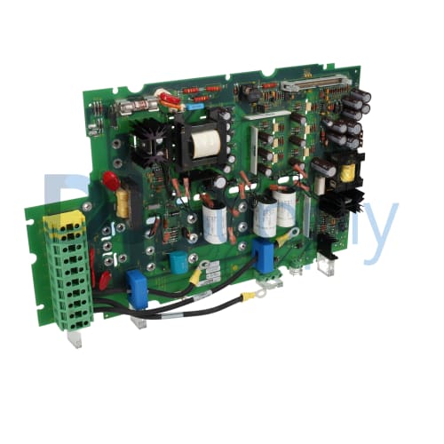
1336-BDB-SP13D
The 1336-BDB-SP13D gate drive board from Allen Bradley is designed to operate seamlessly with a variety of drives. It supports a voltage rating of 230 VAC and is compatible with drives such as the 1336 Plus, Plus II, Force, and Impact.
-
We sell industrial automation parts backed by our free 2-Year DO Supply Warranty.
-
Same-day domestic and fast international shipping with UPS, FedEx, DHL, and more.
-
AMEX, Visa, MasterCard, Discover, wire transfer, net terms, and more.
-
Repairs and exchanges are available for all automation products.
- Reseller Options
Drop shipping, blind shipping, and account shipping with no extra fees.
Technical specifications for 1336-BDB-SP13D
| Manufacturer | Allen Bradley |
|---|---|
| Product Type | Gate Drive Board |
| Product Line | 1336 PCB Boards |
| Part Number | 1336-BDB-SP13D |
| Weight | 3.00 lbs (1.36 kg) |
| UPC | 00 662453676852 |
| Voltage Rating | 230 VAC |
| Power Compatibility | 15 HP |
| Frame Size | Size B |
| Compatible With | 1336 Plus, Plus II, Force, and Impact drives |
| Minimum Operating Temperature | 0 °C |
| Maximum Operating Temperature | 40 °C |
| Minimum Storage Temperature | 0 °C |
| Maximum Storage Temperature | 40 °C |
| Operating Humidity | 80 % (Non-Condensing) |
| Storage Humidity | 80 % (Non-Condensing) |
| Installation Altitude | 1000 MSL |
The Allen Bradley 1336-BDB-SP13D is a specialized gate drive board intended for use in various applications requiring precise control. Its voltage rating is set at 230 VAC, making it suitable for substantial tasks. This board can handle up to 15 HP, contributing significant power compatibility across different setups.
Frame Size B accommodates this gate drive board, while its design ensures it integrates well with products like the 1336 Plus, Plus II, Force, and Impact drives. Operating conditions for the unit specify a minimum temperature of 0 °C and a maximum of 40 °C, which allows for a reliable performance range in typical industrial environments.
Concerning humidity, the board is designed to function properly within an 80% non-condensing range during operation, and the same applies during storage. It is also crucial to ensure that the installation altitude does not exceed 1000 meters above sea level, as this maintains optimal functionality. With these specifications, the 1336-BDB-SP13D is engineered for dependable and effective operations in its proper applications.
- 1336-8D8-SP13D
- 1336-8DB-SP13D
- 1336-BD8-SP13D
- 1336-BDB-SPI3D
- 13368D8SP13D
- 13368DBSP13D
- 1336BD8SP13D
- 1336BDBSP13D
- 1336BDBSPI3D
- I336-8D8-SPI3D
- I336-BDB-SP13D
- I336-BDB-SPI3D
- I3368D8SPI3D
- I336BDBSP13D
- I336BDBSPI3D