Product image is representative; revision or series may vary. Contact us to request a specific version.
1794-CE1
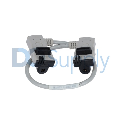
The 1794-CE1 is an extender and interconnect cable from Allen Bradley’s Flex I/O 1794 series, designed to connect FLEX I/O adapters and terminal bases. This cable measures 0.3 meters (1 foot) in length and features a male-to-male 15-pin D-shell connector, ensuring compatibility with various devices.
-
We sell industrial automation parts backed by our free 2-Year DO Supply Warranty.
-
Same-day domestic and fast international shipping with UPS, FedEx, DHL, and more.
-
AMEX, Visa, MasterCard, Discover, wire transfer, net terms, and more.
-
Repairs and exchanges are available for all automation products.
- Reseller Options
Drop shipping, blind shipping, and account shipping with no extra fees.
Technical specifications for 1794-CE1
| Manufacturer | Allen Bradley |
|---|---|
| Product Type | Extender/Interconnect Cable |
| Product Line | Flex I/O 1794 |
| Part Number | 1794-CE1 |
| UPC | 612598129072 |
| Weight | 0.44 lbs (0.20 kg) |
| Input/Output Compatibility | FLEX I/O adapters and terminal bases |
| Cable Length | 0.3 m (1 ft) |
| Connector Type | 15-pin D-shell male-to-male |
| Shielded Connector | Yes |
| Operating Temperature | 0 to 60 °C (32 to 140 °F) |
| Humidity Range | 5 to 95% non-condensing |
| Storage Temperature | -40 to 85 °C |
| Operating Shock | 30g peak acceleration |
| Non-Operating Shock | 50g peak acceleration |
| Vibration | 5g |
The Allen Bradley 1794-CE1 serves as an extender and interconnect cable in automation setups. Designed specifically for compatibility with FLEX I/O adapters and terminal bases, it assures reliable connections in a variety of applications. The cable’s length is 0.3 meters, or roughly 1 foot, which makes it suitable for several setups where space may be limited. It is fitted with a 15-pin D-shell male connector at both ends, ensuring a secure and effective link between devices.
To protect against electromagnetic interference, the 1794-CE1 cable includes shielded connectors, adding an extra layer of reliability in signal transmission. It functions optimally within an operating temperature range of 0 to 60 degrees Celsius (32 to 140 degrees Fahrenheit) and is capable of enduring relative humidity levels from 5 to 95%, as long as it remains non-condensing. For more extreme conditions, the cable can be stored at temperatures ranging from -40 to 85 degrees Celsius.
The design of the 1794-CE1 ensures durability when subjected to physical stress; it can handle an operating shock of up to 30g peak acceleration and a non-operating shock of 50g peak acceleration. Additionally, it withstands vibrations of up to 5g, making it suitable for applications in dynamic environments. Overall, this extender cable offers practical performance for users seeking dependable connectivity solutions in their FLEX I/O systems.
| Revision Part # | Also known as | |
|---|---|---|
| 1794-CE1 Ser A | 1794-CE1/A, Series A, Rev A | |
| Don't see your particular revision? Contact us now. | ||
- 1794-CEI
- 1794CE1
- 1794CEI
- 179A-CE1
- 179ACE1
- I794-CE1
- I794-CEI
- I794CE1
- I794CEI
- I79A-CEI
- I79ACEI
The Allen-Bradley 1794-CE1 Extended-local I/O Cable has a 1 ft. Length.