
1764-24BWA
With the capability to manage a total of 12 relay outputs and featuring two isolated relays per unit, this controller supports 4 high-speed I/O inputs operating at 20 kHz. DIN rail mounting is an opti
In Stock Ships Today
4.9
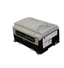
The Allen-Bradley MicroLogix 1500 Programmable Logic Controllers are modularly designed with many components that can be changed to accommodate different application needs in terms of power type and processor capabilities, as well as several components that can be easily added to the devices to increase their scope. The basic elements used to configure these PLCs are base units that include 120 to 240 Volts AC or 24 Volts DC power supplies and 24 or 28 I/Os and processors. When the desired categories of these 2 types of components are selected and physically connected, the devices become fully functional and the items visible on the units are removable terminal blocks, interfaces to expansion modules (hidden behind the plate), groups of input and output status LEDs, device status LEDs, communication ports, batteries, mode switches, and trim potentiometers. Other parts that can be additionally mounted are a memory module, a replacement battery, and a data access tool.
The programming of the Allen-Bradley MicroLogix 1500 small programmable logic controllers is done by using the RSLogix 500 software when the controllers are connected to personal computers. The Allen-Bradley 1769 compact expansion I/O modules can be attached to the device to expand its I/O capabilities. The digital input circuit types on the MicroLogix 1500 devices are 24 Volts DC sink/source or 120 Volts AC inputs, and the digital output circuit types are relays or combinations of relays and FET transistors. To determine the current status of the PLCs, the users have 8 status LEDs which are the power, run, fault, force, battery-low, COMM 0, COMM 1, and DCOMM LEDs. The operating system of the units can be upgraded with a newer one in the controlFLASH upgrade kit.
Browse available units in our catalog of MicroLogix 1500.
With the capability to manage a total of 12 relay outputs and featuring two isolated relays per unit, this controller supports 4 high-speed I/O inputs operating at 20 kHz. DIN rail mounting is an opti

This processor incorporates 14 KB of memory capacity and features two communication ports to facilitate various connectivity options. It supports DF1, DH-485, Modbus, and ASCII communication protocols

This base unit features eight standard 24V DC inputs and eight dedicated fast inputs. It has six relay outputs and includes four standard and two fast 24V DC outputs. High-speed capabilities encompass

Allen-Bradley MicroLogix 1500 with Processor Unit function, 7.6 Kb memory, and DH-485, Modbus, DF1, and ACSII communication

Allen-Bradley MicroLogix 1500 with I/O Rating, 120 Volts AC and 512 Max IO Expansion

Allen-Bradley MicroLogix 1500 with Data Access Tool function, Display Screen feature, and 512 Max IO Expansion

Allen-Bradley MicroLogix 1500 RTC Module with Real-Time Clock and IP20 enclosure

Allen-Bradley MicroLogix 1500 with Memory Module function, 8 Kb memory, and DH-485, Modbus, DF1, and ACSII communication

Allen-Bradley MicroLogix 1500 with Memory Module with RTC function, 16 Kb memory, and Real-Time Clock communication

Allen-Bradley MicroLogix 1500 with Memory Module with RTC function, 8 Kb memory, and Real-Time Clock communication
This section describes how to troubleshoot your MicroLogix 1500 controller. This section will cover the process of understanding your controller LED status, a controller error recovery schematic, and identifying controller faults.
The controller status LEDs provide a way to determine the current status of the controller if a programming device is not present, available, or connected.
| LED | Color | Indicates |
| POWER | Off | No input power |
| Green | Power on | |
| RUN | Off | MicroLogix 1500 controller is not in Run mode or REM Run |
| Green | Controller is in Run mode or REM Run | |
| Green Flashing | System is not in Run mode. Memory module transfer is in process. | |
| FAULT | Off | No fault detected |
| Red Flashing | Faulted user program | |
| Red | Processor hardware fault or critical fault | |
| FORCE | Off | No forces installed |
| Amber | Forces installed | |
| BATTERY LOW | Off | Battery OK |
| Red | Battery needs replacement | |
| COMM 0 | Off | Flashes when communications are active |
| Green | ||
| COMM 1 (1764-LRP only) | Off | Flashes when communications are active |
| Green | ||
| DCOMM*** | Off | User configured communications mode is active |
| Green | Default communications mode active | |
| INPUTS | Off | Input is not energized |
| Green | Input is energized (logic status) | |
| OUTPUTS | Off | Output is not energized |
| Amber | Output is energized. |
***When using a 1764-LRP processor, the DCOMM LED applies only to Channel 0.
The POWER and RUN LEDs are on. If a force condition is present, the FORCE LED turns on and remains on until all forces are removed.
| If the LEDs Indicate | The Following Error Exists | Probable Cause | Recommended Action To Solve |
| All LEDs off | No input power or power supply error | No line power | Verify proper line voltage and connections to the controller. |
| Power supply overload | This problem may occur intermittently if the power supply is overloaded when output loading and temperature varies. | ||
| Power and FAULT LEDs on solid | Hardware faulted | Processor Hardware Error | Cycle power. |
| Loose wiring | Inspect connections to controller to ensure that they are connected. | ||
| Power LED on and FAULT LED flashing | Application fault | Hardware/Software Major Fault Detected |
1. Monitor Status File Word S:6 for major error code. 2. Remove hardware/software condition causing fault. 3. Clear Major Error Halted flag, bit S2:1/13 Attempt a MicroLogix 1500 controller Run mode entry. If unsuccessful, repeat recommended action steps above. |
Use the error recovery schematic below to help you diagnose software and hardware problems in the micro controller. The model provides common questions you might ask to help troubleshoot your system. Refer to the recommended pages within the model for further help.
While a program is executing, a fault may occur within the operating system or your program. When a fault occurs, you have several options to determine what the fault is and how to correct it.
You can automatically clear a fault by cycling power to the MicroLogix 1500 controller when the Fault Override at Power-up bit (S:1/8) is set in the status file. You can also configure the controller to clear faults and go to RUN every time the controller is power cycled. This is a feature that OEMs can build into their equipment to allow end users to reset the controller. If the controller faults it can be reset by simply cycling power to the machine. To accomplish this, set the following bits in the status file:
If the fault condition still occurs after cycling power, the controller reenters the fault mode.
The occurrence of recoverable or non-recoverable user faults can cause the user fault subroutine to be executed. If the fault is recoverable, the subroutine can be used to correct the problem and clear the fault bit S:1/13. The controller then continues in the Run or test mode. The subroutine does not execute for non-user faults. Refer to the MicroLogix 1200 and MicroLogix 1500 Instruction Set Reference Manual publication 1762-RM001 for information on creating a user fault subroutine.
Here at DO Supply, we offer repair services for your Allen-Bradley products, such as the Allen-Bradley MicroLogix 1500 Controller. Please select the Repairs tab for more information or to request a quote.