
2711P-K4M20D
3.5-in. Display Grayscale Keypad - DC 400 Terminal
In Stock Ships Today
4.9
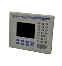
The PanelView (PV) Plus 400 terminals by Allen-Bradley/Rockwell Automation provide advanced tools and capabilities for gaining exceptional control over industrial processes and machinery. These HMI (Human Machine Interface) devices are built for AC or DC operation, offering a level of flexibility that is often needed for industrial applications. The supported voltage ranges are 85 to 264 Volts AC and 18 to 30 Volts DC. The PV Plus 400 series are available with grayscale and color displays, and they feature base-configured units along with communication modules. The greyscale display has a diagonal measurement of 3.8 inches (96.5 millimeters) while the color version has a measurement of 3.5 inches (88.8 millimeters). Both versions have a resolution of 320 x 240 pixels. Also, the PV Plus 400 series provides 2 input options which are a keypad and a combination of a keypad and touchscreen. The analog-resistive touchscreen control option increases user-friendliness and it is designed for bare hand or gloved hand operation. Optimally, the touchscreen should be used with a 1.3-millimeter plastic stylus.
The keypad of PV Plus 400 terminals has 8 programmable function keys, a numeric keypad, and navigation keys. The base unit of the PV Plus 400 terminals come equipped with RS-232 ports, USB ports, Ethernet ports, and modular communications interfaces. The base unit has only an RS-232 port and a USB port. Besides this, the PV Plus 400 terminals have a slot for a very convenient CompactFlash memory card. One of the main advantages of these devices is their capability to communicate through the DH-485, DH+, ControlNet, or isolated RS-232 networks. The modular design of these terminals allows the communication module to be installed on the backside of a device. The PV Plus 400 terminals come with power terminal blocks and 8 mounting levers. Besides that, the terminals have the preloaded and installed FactoryTalk View ME (Machine Edition) software package and similar panel cutouts as the terminals from the PV Standard 550 series.
Browse available units in our catalog of Panelview Plus 400.
3.5-in. Display Grayscale Keypad - DC 400 Terminal

3.5-in. Display Grayscale Keypad - AC 400 Terminal

3.5-in. Display Grayscale Keypad - DC 400 Terminal

3.5-in. Display Color Keypad - DC 400 Terminal
The Panelview Plus 400 has a 3.5 inch Color Display and a Keypad it is AC Powered and communicates via a DH-485 Port
The Panelview Plus 400 has a 3.5 inch Grayscale Display and a Keypad it is DC Powered and communicates via a DH-485 Port

3.5-in. Display Color Keypad/Touch -AC 400 Terminal

3.5-in. Display Color Keypad/Touch -DC 400 Terminal

3.5-in. Display Color Keypad - DC 400 Terminal

3.5-in. Display Color Keypad - AC 400 Terminal
If the PanelView Plus 400 terminal is not starting up correctly always check for adequate power first. Inadequate power can cause a variety of unpredictable behavior. Simply verify the terminal's power requirement in the specifications table. It is also good practice to determine whether there have been any changes since the last startup. Determine what these are to see if they can be reversed.
Battery voltage, as well as the display temperature, are indicative of other potential issues as well. Check the battery voltage and display temperature from the PanelView Plus 400 terminal desktop or from the FactoyTalk View ME station configuration mode. If the voltage is below 2.75 volts DC, consider replacing the battery. Obstructed airflow in the chassis can cause the CPU and/or display to overheat. If the CPU temperature is above 95 degrees Celsius or the display temperature is above 55 degrees Celsius, try to moderate the ambient temperatures.
If you continue have start-up issues, observe the splash screen for state messages and for the status or error codes.
| Message | No. | Meaning |
| RAM Test | 1 | Tests RAM memory |
| Image Search | 2 | Checks for new operating system firmware upgrade on external CompactFlash card and serial port |
| Downloading Image | 11 | Downloads new operating system firmware upgrade to internal RAM |
| Transfer Image | 20 | Programs the operating system firmware recently downloaded into RAM |
| CRC Check | 24 | Checks operating system firmware integrity |
| Decompress System | 27 | Decompresses the operating system firmware into RAM |
| Starting System | 28 | Launches the operating system |
| System Check ### | 29 | Checks internal file system integrity |
| Watchdog Test | 30 | Verifies system integrity by testing watchdog circuitry |
| Message | Error No. | Meaning | Action |
| RAM Test | 1 | Failed RAM Test | Reset the terminal. If the error continues, reset SO-DIMM RAM module. If this does not fix the issue, replace the terminal |
| Stuck Touch | 3a | Failed Touchscreen | Ensure nothing is pressing against the screen. Reset the terminal without using the touchscreen. If the error continues, replace the terminal. |
| RAM Header Check | 14 | Downloading Operating System Firmware Incompatible with Hardware | Check which firmware upgrade is compatible with the terminal. Reset the terminal then upgrade using the correct firmware. |
| Transfer Image | 20 | Failure Programming Downloaded Operating System Firmware into Flash | Reset the terminal. Upgrade the firmware again. If the issue continues, the terminal must be replaced. |
| Download Task | 23 | Operating System Firmware Downloading is too Large | Verify the firmware is the correct version and type. Reset the terminal, the upgrade using the correct firmware. |
| CRC Check | 24 | Checksum of the OS firmware failed. | Reload firmware. If the error continues, replace the internal CompactFlash. If this does not fix the issue, replace the terminal |
| Invalid Prod Family | 25 | Operating System Firmware Downloading is Incompatible with Terminal | Verify the firmware is the correct version and type. Reset the terminal, the upgrade using the correct firmware. |
| Decompress System | 27 | Problem Decompressing Operating System Firmware from Flash to RAM | Reload the correct firmware. If the issue continues, replace the terminal |
| Watchdog Test | 30 | Watchdog test failure | Reload firmware. If this does not fix the issue, replace the terminal |
| Stuck Key | 31 | Function key failure | Verify nothing is pressing any keys. Reset the terminal (do not use key presses). If this does not fix the issue, terminal |
| EXE Check | 40 | System OS firmware is missing or corrupt. | Reload firmware. If the error continues, replace the internal CompactFlash. If this does not fix the issue, replace the terminal |
Status indicators are located on the back of your PanelView 400 terminal. The COMM indicator is green and reflects communication. The FAULT indicator is red and reflects hardware faults. Upon startup, the fault indicator should be off and the comm indicator on. If the fault indicator flashes a few times at startup, this is not a concern. However, if both indicators are off you should check the power cable. See the table below to interpret the terminal's indicator status:
| Fault Indicator (RED) | Comm Indicator (GREEN) | Meaning and Action |
| Possibly Recoverable Error | ||
| Blinking | On | Windows CE Operating System failed or missing. Reload firmware. |
| Off | Most recent firmware download failure. Reload firmware. | |
| Blinking | EBC boot loader firmware missing/failed. Reload firmware. | |
| Fatal Error | ||
| On | Blinking | Fatal display hardware error. Replace terminal. |
| Off | Fatal hardware error. Replace terminal. | |
| Issue | Action |
| Dim or Unreadable Display |
Check contrast settings - When in configuration mode, select Terminal Setting>Display>Display Contrast |
| Backlight Unexpectedly Turning Off or Dimming |
Check screen saver settings - When in configuration mode, select Terminal Settings>Display>Screen Saver |
| Issue | Action |
| Touch Screen Operating Incorrectly/Inaccurate Input and Dragging |
Calibrate Your Touch Screen - When in configuration mode, select Terminal Settings> Touch Screen>Calibration |
| Screen Cursor Not Visible |
Verify the Cursor is Enabled - When in configuration mode, select Terminal Settings> Input Devices> Touch Screen > Cursor |
| Touch Screen Not Accepting Touch Input |
Attach USB Mouse: Mouse works but touch screen does not: Touch driver or screen is nonfunctional Neither mouse nor touch screen working: Application issue |
If the PanelView Plus 400 display lacks a touch screen, you may not have a touch screen display. Check the label on the terminal and the part number of the unit to verify.
Please Note: When calibrating your touch screen, the process requires four (4) screen touches. If the touches are not satisfactory, more will be requested until calibration is successful. If the touch screen does not calibrate or continues to malfunction replace the PanelView Plus 400 terminal.
| Issue | Action |
| Mouse Operating Incorrectly | Reattach USB mouse, restart terminal |
| Cursor Not Visible/Mouse Settings Require Adjustment |
Verify the Cursor is Enabled - When in configuration mode, select Terminal Settings>Display>Cursor Check Mouse Settings - When in configuration mode, select Terminal Settings>Input Devices>Mouse |
| Mouse is Composite Device (Keyboard and Mouse) | Replace with standalone mouse |
| USB Mouse Non-Operational | Replace the USB mouse. Current mouse may be noncompliant |
| Issue | Action |
| Keyboard Operating Incorrectly | Reattach the USB keyboard, restart the terminal |
| Keyboard Rejecting Key Input |
Check Keypad Input - If keypad works either the keyboard driver or keyboard stopped working. If neither the keypad nor the keyboard work, an application failure is likely |
| Keyboard is USB Composite Keyboard and Mouse | Simply use a standalone USB keyboard |
| USB Keyboard is Non-Operational | Replace the USB keyboard. Current keyboard may be noncompliant |
| Keyboard Not Enabled |
Check Alt-Ctrl Keys When in configuration mode, select Terminal Settings>Input Devices>Keyboard |
| Issue | Action |
| Keypad Not Accepting Input |
Check Keyboard Input- If the keyboard works either the keypad driver or keypad stopped working. If neither the keypad nor the keyboard work, an application failure is likely |
| Hold-Off Delay too Long/Multiple Key Presses Inhibited by Multi-Key Lockout |
Check Keypad Settings- When in configuration mode, select Terminal Settings>Input Devices>Keypad Note: Home, End, Up and Down keys do not work when single or multi-key lockout is enabled. |
Examine the status indicators at the Ethernet connector. If the indicator is green, a communication link is on. If the indicator is an amber color and flashing, this indicates data activity. You should always ensure there is a good connection to the hub and uplink ports. Poor cable quality and crimping can inhibit the ethernet connection.
When in configuration mode select Terminal Settings> Networks and Communications > Network Connections > Network Adaptors. Check the DHCP. If this is enabled the device will attempt to connect to a valid IP address within seconds of startup. If it fails to acquire and IP address, the TCP/IP protocol will assign 169.254.xxx.xxx. If the DHCP is not enabled, verify the IP address specified does not conflict with another device on the network.
Other devices must not share the same hostname if they are on the same network. When in configuration mode, select Terminal Settings> Communications and Networks> Network Connections> Device Name.
The Ethernet issue may be caused by the other side of the connection.
Here at DO Supply, we offer repair services for your Allen-Bradley products, such as the Allen-Bradley PanelView Plus 400. Click here for more information or to request a quote.