
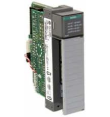
1746-OW16
The 1746-OW16 module is part of the SLC 500 series, offering 16 digital outputs and configured for normally open signaling. Each common can manage 8 output points, making it efficient for varied contr
In Stock Ships Today
4.9
The SLC 500 programmable controller series combines power with flexibility by offering a wide range of communication configurations, features, and memory options at an affordable price. The controllers utilize ladder-logic and structured-text programming to provide exceptional productivity and a smooth user interface. The broad selection of I/O modules, along with Ethernet, DH+, DH-485, ControlNet, and DeviceNet communication capabilities, makes SLC 500 controllers some of the most versatile on the market. Additionally, the SLC 500 series boasts an advanced instruction set, including file handling, sequencer, diagnostic, shift register, immediate I/O, and program control instructions. The modularity of the series offers many customization and configuration options, including but not limited to: adding I/O, memory, or communication interfaces. The SLC 500 modules even include backup options for increased fault tolerance via the ControlNet Hot Backup module or the PLC-5 Backup Communication module. If you are looking for a programmable controller that seamlessly combines power, flexibility, and affordability, then the SLC 500 series is for you.
Browse available units in our catalog of SLC 500.
The 1746-OW16 module is part of the SLC 500 series, offering 16 digital outputs and configured for normally open signaling. Each common can manage 8 output points, making it efficient for varied contr

This power supply module is designed for chassis mounting and supports rack mounting features. It operates effectively within a temperature range of 0 to 60 degrees Celsius and can be stored at temper

This analog input module accommodates 8 inputs and offers various input types, including high-impedance differential and single-ended options. Voltage input ratings include -10 to 10V DC and 0 to 10V

With an input capacity maxing out at 4096 and an output capacity of the same amount, the 1747-L552 accommodates complex system needs effectively. Furthermore, it supports up to 480 local analog I/O po

This high-resolution input module features a total of four inputs with a voltage input range of -10 to 10V DC and a current input range of -20 to 20 mA. It operates effectively at a backplane current

With a maximum local analog I/O capacity of 480 I/O points, the 1747-L553 allows for substantial input/output management. Typical program scan times are calculated at 0.9 ms per Kword, and I/O scan ti

This processor is designed with a total user memory of 16K words, containing 12K words designated for programs and 4K words solely for data. It can accommodate up to 4096 inputs and 4096 outputs, incl

This output module operates within an extensive temperature range from 0 to 60 degrees Celsius while being capable of storage in environments as low as -40 degrees Celsius and as high as 85 degrees Ce

This input module operates at a nominal voltage of 24V DC and handles a total heat dissipation of 3.6 watts. Each input channel effectively manages a heat dissipation of 0.2 watts, with a maximum sign

This processor operates at a maximum load current of 0.5 Amps at 5V DC and 0.175 Amps at 24V DC. It is designed to accommodate a total power consumption of 2.9 Watts. It supports up to three chassis a
The SLC 500 series is a series of Allen-Bradley programmable logic controllers that are used for a wide variety of applications. The SLC 500 series features Ladder-Logic with a structured text programming. The units are designed for addressing a broad range of applications that include file handling, sequencer, diagnostics, shift register, and immediate I/O and program control instruction applications. The SLC 500 controllers support built-in RS-232, 422, and 423 communication ports. The unit also comes with the DeviceNet and the ControlNet I/O on the selected processors. The SLC 500 series provides controllers that have powerful and affordable performance. These units are designed and built to provide excellent value.
The Allen-Bradley SLC 500 controllers feature modular processes, power supplies, I/O devices, memory options, and communication interfaces that allow the units to have configurable and expandable systems. The units feature an advanced instruction set that includes indirect addressing and a high level of performance capability for delivering computation instructions. The units are programmed to provide the users with a broad selection of the I/O devices. Therefore, the users can select from over 60 modules that help to control the discrete, analog, and temperature signals. The SLC 500 controllers are designed to deliver power and flexibility with a wide range of communication configurations. The SLC 500 modular hardware style controllers allow for the section of the processor, power supply, and I/O modules. The units also come with optional memory modules that provide a non-volatile memory in a convenient modular form. When using the commercial PROM programmers for programming and erasing the memory module, adapter sockets are required.
SLC 500 troubleshooting
Ensure the card is slid into the rack allowing both bottom and top clips to lock into place
Check that the entire rack has power
Allow a 1-5 min power cycle
Check pins on the back side of the card where a connection is made into the rack
Take the card out and do a visual inspection of the card outside of the rack, checking that resistors, capacitors, TRIACs and chips all look functional
Check to see that power supply is screwed into the rack and properly mounted
Make sure your RS-232 cable is making a good connection with both the computer and processor
Check that the proper COMM port and driver is being used in RS-Linx
For SLC 5/03 and up apply screwdriver across GND and VBB for 1 min, this will reset COMMS
Check to ensure you are reading the correct driver in rs-linx
Research error codes
Check power supply
Try inserting power supply into another rack
Check voltage going into power supply and ensure correct sumpers are selected if there any
Check pins on the back slide of the power supply that plug into the rack
Check manual for proper insulation and power requirements for multiple power supplies
Add your amperage rating for each device
If the rack is still not powering on, the application you are using could require more amperage than the supply is rated for
Example:
The 1747-L551 draws 1A at 5v DC
The 1746-OV16 requires 0.270 A according to documentation
The 1746-P2 supplies 5A at 5vDC to the backplane
Checking to see if our power supply can handle the load we would use the following formula:
IT=I1+I2+I3
Using this formula, we can see that since 1a + .27a = 1.27a ,
the 1746-P2 would handle this load no problem
If none of these solutions solve the problem, there could be a faulty card killing your whole rack
Remove each card one at a time to check if there is a card causing issues in the rack