
2098-DSD-020-SE
Allen Bradley-SERVO DRIVE 10AMP/30AMP ULTRA 3000 120/240VAC AB
In Stock Ships Today
4.9
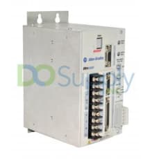
The Ultra 3000-5000 series is a series of Allen Bradley digital servo drives that are built to support simplified stand-alone indexing. The Ultra 3000-5000 series features compact and programmable drives that combine performance and flexibility for ensuring high-speed position capturing and calculations. The Ultra 3000-5000 series drives feature an automatic motor recognition capability and they come with intelligent feedback capabilities. This eliminates the need for configuring the motor parameters. The Ultra 3000-5000 drives’ installation procedure includes determining the drive and the motor or actuator’s catalog number in order to determine the motor power and the feedback cables. The units feature the motor-end connector kits that are used when building cables. During the installation of the Ultra 3000-5000 drives inside an enclosure, the users should run the input power wiring in conduits outside of the enclosure, and ensure that the signal and power cables are separated.
The Ultra 3000-5000 drives feature an ambient temperature that must not exceed 55 degrees Celsius. They must be installed vertically on panels. In addition, the users should plan the installation of the system and ensure there is adequate ventilation. If the users are using a ventilated cabinet, they should use filtered or conditioned air to prevent the accumulation of dust and dirt on the electronic components. The Ultra 3000-5000 series features drives that contain components that are sensitive to electrostatic discharge. Therefore, the installers should ensure that all the static control procedures are adhered to. For drive communication, the Ultra 3000-5000 drives come with serial port connectors and I/O connectors. The units support motor encoder signals from incremental encoders with TTL outputs and the intelligent absolute encoders.
Browse available units in our catalog of Ultra3000-5000.
Allen Bradley-SERVO DRIVE 10AMP/30AMP ULTRA 3000 120/240VAC AB

Allen Bradley-DRIVE 5/15AMP ULTRA 3000 ANALOG AB

Allen Bradley-HIGH VOLTAGE DRIVE, 34A/68A, ULTRA3000 W/SERCOS AB

Allen Bradley-SERVO DRIVE ULTRA3000 10/30AMP AB

Allen Bradley-SERVO DRIVE 15/30AMP 120/240VAC 50/60HZ ULTRA3000 AB

Allen Bradley-SERCOS DRIVE,5.0A/15A, ULTRA 3000 AB

Allen Bradley-DRIVE, 10A/30A, ULTRA3000 W/DEVICENET/INDEX AB

Allen Bradley-HIGH VOLTAGE DRIVE, 11A/22A, ULTRA3000 W/SERCOS AB

Allen Bradley-HIGH VOLTAGE DRIVE, 47A/94A, ULTRA3000 W/SERCOS AB

Allen Bradley-SERCOS DRIVE 2.5-7.5AMP ULTRA 3000 120/240VAC AB
| Error Code | Problem or Symptom | Possible Cause(s) | Action/Solution |
| -- | PWR (Power) indicator not ON |
1. No AC power or auxilary logic power 2. Internal power supply malfunction |
1. Verify AC power or auxiliary +5 volt logic power is applied to the Ultra3000 |
| -- | PWR (Power) indicator is ON, but seven-segment LED display is OFF. (Applicable to 2098-DSD-005, -010, and -020 Ultra3000 models only). | Externally applied +5V auxilary power supply voltage is too low | Ensure that the external +5 volt auxilary power supply (measured at the drive terminals) reads between 5.10 volts and 5.25 volts. |
| -- | Motor jumps when first enabled |
1. Motor wiring error 2. Incorrect motor chosen |
1. Check motor wiring 2. Verify the proper motor is selected |
| -- | Digital I/O working incorrectly | I/O power supply not connected | Check connections and I/O power source |
| E01 | Non-volatile Memory Endurance Exceeded | Range of motion and number of home position definitions during the product life exceeds the maximum allowed (systems with absolute feedback). | Unrecoverable failure. Replace the drive. |
| E02 | Velocity Exceeds Position Rollover /2 | The velocity command or feedback exceeds half the machine cycle length per milisecond (when the machine cycle position rollover is enabled) | Increase machine cycle size or reduce velocity profile. (Firmware versions prior to 1.10). |
| E03 | Absolute Feedback Range Exceeded | The motor position exceeds +/- 2047 revolutions from the home position (systems with absolute feedback). |
Decrease application range of motion. Upgrade firmware. |
| E04 | Motor Overtemperature |
1. Motor thermostat will trip due to high motor ambient temperature and/or excessive current. 2. Motor wiring error 3. Incorrect motor selection |
Operate within (not above) the continuous torque rating for the ambient temperature (40° Celsius maximum) |
| E05 | IPM Fault |
1. Motor cables shorted 2. Motor winding shorted internally 3. Ultra 3000 temperature too high 4. Operation above continuous power rating 5. Ultra3000 has a bad IPM output, short, or overcurrent 6. Drive was enabled without waiting 1.0 seconds after applying the main AC power. (2098-DSD-005, -010, and -020 Ultra3000 models using an external +5 volts auxilary power supply) |
1. Ensure continuity of motor power cable and connector. 2. Disconnect motor power cables from the motor. If the motor is difficult to turn by hand, it may need to be replaced. 3.a. Check for clogged vents or defective fan. 3.b. Ensure cooling is not restricted by insufficient space around the unit. 4.a. Ensure ambient temperature is in the correct temperature range. 4.b. Operate within the continuous power rating. 4.c. Reduce acceleration rates. 5. Remove all power and motor connections, check for continuity from the DC bus to the U, V, and W motor outputs. If a continuity exists, check for wire fibers between terminals, or send in drive for repairs. 6. Wait at least 1.0 second after the main AC is applied before enabling the drive. |
| E06 | Hardware Overtravel (SERCOS) | Inactive dedicated overtravel input. | Inspect wiring and/or verify motion profile. |
| E09 | Bus under voltage | Low AC line/AC power input | Check voltage level of the incoming AC power, check the AC power source for glitches or line drop, or install and uninterruptible power supply (UPS) on your AC input. |
| E10 | Bus over voltage |
1. Excessive regeneration of power. When the motor is powered by an external mechanical power source, it may regenerate too much peak energy through the Ultra3000's power supply. The system will fault to save itself from an overload. 2. Excessive AC input voltage. |
1. Change the deceleration or motion profile, use a larger system (motor and Ultra3000), use a resistive shunt, or, if a shunt is connected, verify the wiring is correct and the shunt fuse is not blown. 2. Verify input is within product specifications |
| E11 | Illegal Hall State |
1. Incorrect phasing 2. Bad connections |
1. Inspect the Hall phasing. 2. Verify the Hall wiring and the 5 volt power supply to the encoder. |
| E12 | Home search failed | Home sensor and/or marker is outside the overtravel limits. | Inspect wiring, and reposition the overtravel limits or sensor. |
| E13 | Home Position In Limit | Home sensor, marker, or final home position exceeds a hardware overtravel limit. | Reposition the overtravel limits or home sensor, or adjust the final home position. |
| E14 |
1. SERCOS Hardware Failure (SERCOS only) 2. DeviceNet Communications Network problem (DeviceNet drives only) |
1. A failure was detected in the operation of the drive's internal SERCOS hardware 2. DeviceNet communications network is broken |
Troubleshoot DeviceNet communications. |
| E15 | Excessively Long Electrical Cycle | Electrical cycle length exceeds maximum lines per electrical cycle | Replace the linear motor or encoder |
| E16 | Software Overtravel (SERCOS) | Programmed overtravel limit exceeded | Check the motion profile or make sure overtravel settings are appropriate. |
| E17 | User-Specified Current Failure | User-Specified average current level exceeded | Increase to a more permissive setting |
| E18 | Overspeed Failure | Motor speed exceeded 125% of maximum rated speed. | Inspect cables for noise or inspect tuning. |
| E19 | Excess Position Error | Position error limit exceeded | Increase the feed-forward gain, increase the following error limit or time, or inspect position loop turning. |
| E20 | Motor Encoder State Error |
1. Motor encoder encountered an illegal transition. 2. Faulty encoder |
1. Replace the motor/encoder, use shielded cables with twisted pair wires, route the feedback away from potential noise sources, check the system grounds, ensure that the unbuffered encoder signals are not exposed to EMI in the CN1 cable, and remove these signals from the CN1 cable if they are not being used, check to make sure that the motor has a high frequency bond to the drive's enclosure panel, and verify that any stage connected to the motor shaft, for example, using a ball screw, has a high frequency bond to the machine frame and the drive's enclosure panel. 2. Replace motor/encoder |
| E21 | Auxilary Encoder State Error |
1. The auxilary encoder encountered an illegal transition. 2. Setup time violation for Step/Direction or CW/CCW input |
1. Use shielded cables with twisted wire pairs, route the encoder cable away from potential noise sources, possible faulty encoder, needing replacement, or check ground connections. 2. Check the timing of Step/Direction or CW/CCW inputs to determin if setup time requirements are being met. |
| E22 | Motor Thermal Protection Fault | The internal filter protecting motor overheating has tripped | Reduce acceleration rates, reduce duty cycle (ON/OFF) of commanded motion, increase time permitted for motion, use larger Ultra3000 and motor, or inspect tuning. |
| E23 | IPM Thermal Protection Fault | The internal filter protecting drive overheating has tripped | Reduce acceleration rates, reduce duty cycle (ON/OFF) of commanded motion, increase time permitted for motion, use larger Ultra3000 and motor, or inspect tuning. |
| E24 | Excess Velocity Error | Velocity error limit exceeded | Increase time or size of allowable error, reduce acceleration, or inspect tuning. |
| E25 | Senor Not Assigned | Homing or registration motion was attempted without a sensor assigned | Assign a sensor to a digital input |
| E26 | User-Specified Velocity Failure | User specified velocity level was exceeded | Increase to a more permissive setting |
| E27 | Axis Not Homed | Absolute positioning was attempted without homing | Verify homing sequence |
| E28 | Motor Parameter Error | Parameter loaded from smart encoder or received from SERCOS controller is not compatible with the drive | Select a different motor through the SERCOS controller or select a different motor |
| E29 | Encoder Output Frequency Exceeded | Encoder output frequency exceedes the maximum user designated value (when encoder output is synthesized by the drive) | Increase the encoder output maximum frequency parameter, decrease the encoder interpolation parameter, or increase the encoder output divider parameter. |
| E30 | Encoder Communication Fault | Communication was not established with an intelligent encoder. | Verify motor selection, verify the motor supports automatic identification, and verify motor encoder wiring. |
| E31 | Encoder Data | Encoder data is corrupted | Replace the motor/encoder |
| E32 | Sine and Cosine Encoder Frequency Limit Exceeded | Maximum frequency of the sine and cosine ciruitry has been exceeded | Decrease velocity, or use encoder with a slower resolution before interpolation. |
| E33 | Absolute Position Exceeds Position Rollover | Motion is commanded to a position outside the position rollover range. An absolute index is started that specifies a position outside the position rollover range, a homing cycle is started with the home position outside the position rollover range, a define home is started with the home position outside the position rollover range, or a preset position is initiated that specifies a position outside the position rollover range. | Designate motion command to a position within the position rollover range. |
| E34 | Ground Fault |
1. Wiring Error 2. Motor internal ground short 3. Internal malfunction |
1. Inspect motor power wiring 2. Replace motor 3. Disconnect motor power cable from drive and enable drive with current limit set to 0. If failure clears, then a wiring error or motor internal problem exists. |
| E35 | Precharge gailure |
1. Low AC input voltage 2. Internal malfunction |
Inspect input AC voltage on all phases |
| E36 | Power Circuitry Overtemperature | Excessive heat exists in the power circuitry | Reduce acceleration rates, reduce duty cycle (ON/OFF) of commanded motion, increase time permitted for motion, use larger Ultra3000 and motor, and inspect tuning. |
| E37 | AC Line Loss | One or more phases of the input AC power is missing | Inspect input AC voltage on all phases |
| E39 | Self-sensing Commutation Startup Error | Motion required for self-sensing startup commutation was obstructed | Verify that there are no impediments to motion at startup, such as hard limits, increase self-sensing current if high friction or load conditions exist, and inspect motor or encoder wiring using wiring diagnostics. |
|
E40 |
E40: 230 volt Shunt Protection Failure |
1. Ineffective shunt resistor 2. Excessive regeneration |
Verify that the internal or external shunt resistor is connected. If an external shunt resistor is connected, verify that the shunt fuse is not blown. Check compatibility of external shunt resistor is used; check that the resistance value is within product specifications. Confirm that the motor is not being driven mechanically, causing the motor to behave as a generator. |
| E41 | 460 volt Shunt Protection Failure |
1. Ineffective Shunt Resistor 2. Excessive Regeneration |
Verify that the internal or external shunt resistor is connected. If an external shunt resistor is connected, verify that the shunt fuse is not blown. Check compatibility of external shunt resistor is used; check that the resistance value is within product specifications. Confirm that the motor is not being driven mechanically, causing the motor to behave as a generator. |
| E42 | Motor Keying Error (SERCOS only) | The motor physically connected to the drive differs from the motor specified in the user program. | Select the correct motor in the user program. |
| E43 | Drive Enable Input (SERCOS) | An attempt was made to activate the axis through software while the Drive Enable hardware input was inactive, or the Drive Enable input transitioned from active to inactive while the axis was enabled. | Disable the Drive Enable Input failure, and verify that Drive Enable hardware input is active whenever the drive is enabled through software. |
| E50 | Duplicate Node Fault (SERCOS) | Duplicate node address detected on SERCOS ring | Ensure that each SERCOS is assigned a unique node address |
Here at DO Supply, we offer repair services for your Allen-Bradley products, such as the Allen-Bradley Ultra 3000-5000. Please select the Repairs tab for more information or to request a quote.