Allen-Bradley Communication Types and Protocols
Industrial automation has long been at the heart of many of the improvement in manufacturing and process efficiencies across many industries. And the ability to use standardized applications to control devices and equipment at a speed and precision greater than that possible by human range of motion and reaction is one of the key reasons for that reality.
As the digital revolution as grown, it has ushered in an accelerated need for improved and evolving control over such devices to handle new capabilities and new inputs from a data stream that is growing exponentially. Even more than a smart home or a connected individual, factories, warehouses, and supply chains are becoming more and more connected to leverage this connectivity to add value to their processes and improve competitiveness. As a result, the sophistication and capability of the communication types and protocols used to drive PLCs and other control equipment has grown and evolved as well. In this article we’ll cover the following communication protocols:
- Ethernet/IP
- DeviceNet
- ControlNet
- Remote I/O
- Serial
- DH+
- DH 485
- Profibus
- ASCII
- Modbus
An Increasingly Busy Intersection
As connectivity becomes a business imperative driven by initiatives such as Industry 4.0, different devices and interface types need to be connected in a way that can be scaled to meet the growing needs. They must also be linked efficiently to allow the movement of data and the proper responses to the equipment they drive.
There are four basic elements in today’s industrial automation schemes. These include Programmable Logic Controllers (PLC), Human Machine Interfaces (HMI), motor control points and the various sensors and detectors needed to trigger robotic or mechanical functions to complete tasks. These elements are like cars approaching a busy intersection at high speed. They need accurate, fast, and safe communication protocols to act as the stop signals, highway signs and traffic cops to ensure safe interaction at the point of intersection.
- PLC – The PLC is the ubiquitous workhorse of the automation world. Ranging from a few input/outputs (I/O) to rack mounted versions that can support hundreds of I/Os, PLCs require a physical layer to connect it servers, HMIs, and other devices. It also requires a shared protocol. This protocol acts as a common language, so each device understands what the bits of data mean as they arrive.
- Human Machine Interfaces – In today’s automated environments, HMIs are the point at which the operator or technician interacts with the machine, the communication system, and the programmed variables to complete tasks. These command input interfaces are intuitive and often WYSIWYG in configuration, requiring accurate programming and communication to translate these commands into actions understood by the other elements.
- Motor Controls – These are the control points where the motor is instructed to engage or disengage based on the inputs form the HMI and instructions from the PLC.
- Sensors and Detectors – In an automation network, sensors and detectors are deployed at the action end of the equipment, instructing mechanical devices to complete a task. This can include devices such as weight scales, light or IR scanners, temperature sensors and a host of other devices that drive the “limbs” of the equipment to perform tasks.
Different Protocols for Different System Needs
With this complex intersection of devices, it is critical that all speak the same “language” and that the protocols used in reconciling I/Os and the meaning of the data to manage the traffic and communicate appropriate instructions. However, each automation system is different. They may range from the simple to the complex depending on end use and industry. They may also require specific safety levels or redundancies, again differing from industry to industry.
As a result, there are different types of communication and protocols depending on system needs. Many can work in conjunction or they may stand alone. And each system of controls must be evaluated to determine which type of communication protocol is required.
Here are some of the most common communication types and protocols that are currently available for automation control systems:
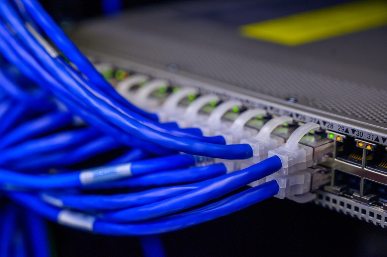
Ethernet
Ethernet is one of the oldest communication systems used for industrial automation. It is a networking technology that can be used in both Local Area Networks (LAN) as well as Wide Area Networks (WAN). Ethernet originally consisted of coaxial cable that ran throughout an operation and connected machines physically. This not only created the possibility of collisions of data traversing the cable, it also limited bandwidth depending on the number of devices attempting to communicate at one time.
As the system matured it was standardized across the control industry internationally and has continued to evolve. Today, ethernet systems have a much higher bandwidth and sport better medium access control (MAC) methods. The MAC layer controls the hardware tasked with interacting with wired, optical, and wireless elements of the system. This evolution also saw the upgrade from coaxial cable to point-to-point links that are connected by Ethernet repeaters, or switches.
Ethernet systems used today are collision free because they use duplexing capability. This is due to advanced functionality that allows switches and stations along the network to send and receive data simultaneously. This has also improved utilization of bandwidth for system segments in the network. Speeds have also improved, moving from a mere 10 megabits per second (Mbps) on the older coaxial configuration to speeds as high as 1 gigabit per second (Gbps) using twisted pairs.
Using Industrial Ethernet Protocols
While there are many different Ethernet protocols, one of the most common used in industrial automation applications today is Ethernet/IP. Ethernet/IP is used in both discreet and process automation needs. Ethernet/IP is part of a group of network systems that utilize the Common Industrial Protocol (CIP) in its upper layers. It is managed by the Open Device Vendors Association (ODVA) and follows the Open Systems Interconnection (OSI) model. Here, the framework for a network is divided into seven layers including physical, data link, network, transport, session, presentation, and application. By utilizing this hierarchy of layers, functionality of the network can be defined from physical implementation through user interface.
The use of Ethernet/IP can be considered as follows: With the Ethernet acting as the physical networking protocol, that links elements to the system, Ethernet /IP is specifically an industrial communication protocol used in industrial automation systems. Ethernet networks offer a large and flexible number of nodes. Because Ethernet/IP uses CIP over the Ethernet, it can establish connections from one application node to another. It can also with a CIP connection using a Transmission Control Protocol (TCP). It also allows multiple CIP connections with a single TCP connection.
Advantages of Ethernet/IP
As a mature networking system, Ethernet/IP has several advantages over other systems. These include:
- Common Protocol – Ethernet/IP uses a proven and long used system – Ethernet – to provide industrial automation. It uses the transport and control protocols common in a traditional Ethernet structure.
- CIP – Because Ethernet/IP uses CIP as its core, it can align with DeviceNet and ControlNet devices and allow a wide range of devices to be accessed via a common mechanism. This allows it to work over larger networks without having to reconcile communication.
- Data Volume – Ethernet allows the transfer of larger amounts of data compared to other systems. This functionality aligns well with the proliferation of edge devices and sensors used in the deployment of Industrial Internet of Things (IIoT) technology which relies on a vast data stream to leverage the power of AI, deep analytics and machine learning algorithms.
- Device Compatibility – Because Ethernet/IP is such a common communication protocol, it allows devices from different manufacturers to be connected easily. In the past, control systems tended to be proprietary and changing components could be tricky. With the proliferation of Ethernet/IP, device compatibility is not an issue.
Disadvantages of Ethernet/IP
- Increased Security Concerns – Using Ethernet/IP increases bandwidth connects the entire manufacturing system to the network. This makes it critical that automation engineers must take security into account for the design of the system to ensure system integrity.
- Diagnostics – Ethernet/IP devices do not contain generic diagnostics. This means that like security, diagnostic capabilities will need to be included in system design.
- Device Replacement – There is no current SOP for device replacement for Ethernet/IP. Components used for replacement will have to be reconfigured as they were in the original build.
DeviceNet
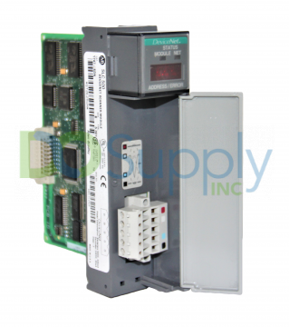
Like Ethernet/IP, DeviceNet is an open network that uses the Common Industrial Protocol (CIP) to control, configure and collect data used in industrial devices. DeviceNet is an application-level communication protocol that is often used for industrial automation. It sits atop the Controller Area Network (CAN) and allows connections between simple, usually machine level, devices, and higher-level devices such as PLCs. DeviceNet is limited to a total of 64 nodes and is predominantly used for discrete applications within manufacturing.
In DeviceNet, up to 64 devices can be placed on a single node. These devices usually have simple functionality with low data requirements such as on/off switches, sensors, and other straightforward control systems. Because its function is I/Os at the machine level, bandwidth requirements are lower for DeviceNet than Ethernet/IP and Control/Net.
Depending on end use and application, one key advantage of DeviceNet is that power and signal are provided in one cable. This gives it a cost advantage over other protocols and is highly useful in the connection of legacy equipment in IIoT deployments when connectivity is not native to the machine from the OEM.
DeviceNet also uses a trunk and dropline system allowing devices to be added to a total of 64. This significantly reduces installation time and helps when needing to add devices to the system. And since DeviceNet routes all 64 devices through a single node, troubleshooting and maintenance are easier by comparison.
DeviceNet has a server/client network with support for peer-to-peer communications and uses 11-bit identifiers in message headers. Transmission speeds range from 125 Kbps to 500 Kbps. Network length may create a tradeoff in speed depending on total length. For example, for short runs for 200-300 feet, 500 Kbps can be realized, while runs up to 1,640 feet will require thick cable and lower speeds of around 125 Kbps.
Advantages of DeviceNet
DeviceNet is great for specific applications and best for discreet environments. This includes industries such as material handling, packaging, food and beverage machine tools, and others. Advantages include:
- Reduced Set-Up and Installation Time – Because of the trunk and drop system, DeviceNet is simple to install.
- Safety Applications – DeviceNet is often used for safety control and is also excellent for quality and regulatory monitoring that may impact safety as well.
- Maintenance – DeviceNet allows the use of smart devices which can save on equipment and maintenance costs at the machine level. And because of its plug-and-play capability, DeviceNet is easier to run diagnostics and troubleshoot.
- Node Capacity – If an installation requires less than 64 devices, adding new devices to the system incrementally to add or enhance system performance makes DeviceNet flexible.
Disadvantages of DeviceNet
The disadvantages of DeviceNet are due to specific limitations that generate lower cost and improved flexibility. They are not qualitative as such but more along the line of disadvantages that should be weighed when considering deployment options during an assessment of needs for building or installing a new system. Those with higher-level data and control needs will use these disadvantages to determine the need for other communication protocols such as Ethernet/IP or ControlNet. Given that qualifier, here are a few of the disadvantages of DeviceNet:
- Limited Message Size – Messages on DeviceNet are limited to a max of 240 bytes each for transmit/receive.
- Significantly Shorter Cable Distance – Max cable distance is limited to 1640 with the requirement of thick cable.
- Lower Bandwidth – The benefits of signal and power within the same cable reduce available bandwidth available for complex or large messages.
- Lower Number of Devices Per Node – While DeviceNet is ideal for simple data acquisition environments or the beginning of an IIoT digital transformation to bring legacy equipment into the data stream, it is still limited to 64 devices on the node.
ControlNet
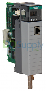
The third in a suite of communication protocols that use CIP, ControlNet is also managed by ODVA and used for industrial automation. Compared to DeviceNet, ControlNet has a higher skillset of capabilities available for more complex data needs used for redundant media and process applications. It is used where the required volume of data is much higher for use in devices such as robotics, motion sensing, motion control and visual controls.
Also, like Ethernet/IP and DeviceNet, ControlNet uses the OSI model on CIP defining network protocols in seven layers. It implements CIP at the session layer and higher but adapts CIP to ControlNet specs at the transportation level and below. This allows it to function as a high-speed network to send time-sensitive I/O that includes configuration data and peer-to-peer data.
For companies who require advanced automation and IIoT control or who are scaling their IIoT to a more sophisticated level, ControlNet has an increased device count of up to 99 devices per node. Because advanced robotics, motion controls, visual controls and other higher-level automated functions require more data and more signal, ControlNet offers a higher data transfer rate of 5 Mbps on an open control network for real-time, high throughput applications.
Both Ethernet/IP and DeviceNet are not deterministic. But the use of high-level automation and robotics often require deterministic, repeatable transfers on all mission-critical control data. With higher data transfer rates and higher data volumes, ControlNet uses this feature to control the data flow by setting exact times of transfer to and from.
Given the increased data requirements, ControlNet cannot allow signal and power on the same cable. Using fiber optics or coax, ControlNet can manage both power and data streams effectively. And when using fiber optics, it is possible to extend the cable run up to 1000 meters without use of a repeater.
ControlNet allows connection of PLCs and HMIs at the floor level to manage beyond simple on/off commands. This higher-level of data management can be used to program automation functions for robotics, visual control quality systems, and other advanced machine functions. This not only provides operational data. It allows data to be passed to ERP systems, IIoT software and other enterprise level analytical systems in real-time to enhance visualization of the manufacturing environment or to improve decision-making.
Advantages of ControlNet
- Deterministic – ControlNet allows the user to set and manage times for critical I/O data. This makes process applications repeatable in both discrete and process applications.
- Safety – It allows intrinsically safe options to meet EU, UL, FM, and other certifications for use in potentially explosive atmospheres.
- Flexibility – Nodes can be removed and replaced under power and anywhere on the network.
- Versatile – ControlNet allows for multiple controllers on one wire, increasing options and allowing better system performance.
Disadvantages of ControlNet
ControlNet offer a higher level of data but comes with some disadvantages depending on end use. These include:
- Higher Hardware Costs – The additional capacity, multiple drop options and use of fiber optic cable result in higher hardware costs overall.
- Maintenance – ControlNet is inherently more difficult to troubleshoot.
- Complex Cabling Requirements – Because it uses one cable for signal and one for power, cabling is more complicated when deploying ControlNet. This complexity increases with length of run and the use of fiber optics over coax.
ControlNet is better suited to handle the complex communication and data needs for IIoT deployments compared to DeviceNet. These applications often include extremely heavy data stream requirements to the IIoT software platform and almost instantaneous inputs to drive the robotics, analytics and automated adjustments that come from the benefit of AI and ML applications in these systems.
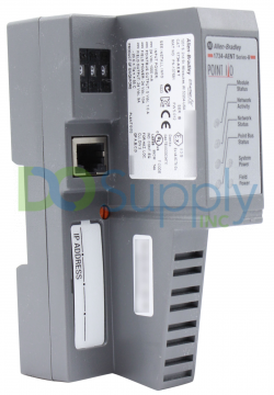
Remote I/O
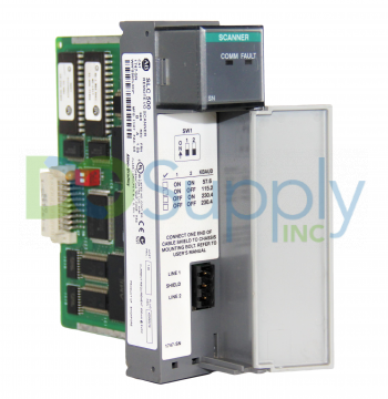
Traditional control systems utilized a local I/O module that were housed in the same cabinet with PLCs. As automation needs grew and solutions became more sophisticated, remote I/O has become more common. Additionally, with the advent of Industry 4.0 and the arrival of IIoT devices, remote I/Os may soon equal or surpass local I/O.
Remote I/O devices are in a physically located distance from the control PLC cabinet. They use transmission over wired or wireless systems to send and receive input and output information to a variety of systems such as personal computers, PLCs, and other control systems. As their popularity and utility has grown, controller manufacturers such as Allen-Bradley have developed universal remote I/O network devices as a LAN solution to connect controllers to a remote I/O chassis for leveraging intelligent devices such as operator interfaces.
As remote I/O devices have proliferated, vendors have added capabilities to make them more agile and flexible. Many offer hardened remote I/Os that can withstand vibration and shock from direct contact with the machine. They have also begun adding onboard logic solving capability to remain compatible with IIoT software capabilities and they also offer versions with several different safety certification ratings such as SIL3, Cat. 4 and PLe.
Remote I/O devices may use adaptor modules connected to the controller backplane in the PLC rack. However, there is a growing capability for wireless and cellular driven remote I/Os as well, making them versatile and flexible for industrial automation applications.
Uses for Remote I/O
Remote I/Os are used for a variety of reasons including:
- Control and Timing – Remote I/Os may send data and receive instructions to trigger actions at the machine level.
- Device Communication – They can be used to report conditions of the machine or equipment for maintenance and breakdowns for reporting in programs for Overall Equipment Effectiveness (OEE).
- Data Buffering – They can be used for data buffering to mitigate issues with bandwidth and large surges of data so that the system can properly handle and process output data in the right order.
- Error Detection – They can trigger action or report faults, stops and other machine related errors as they occur.
Using Remote I/Os with Communication Types and Protocols
Because Remote I/Os are simple electronic network devices designed only to send and receive information, they must use a communication protocol for interaction between the control cabinet and the device itself. Remote I/O devices can work with a variety of communication protocols. This includes protocols using CIP such as Ethernet/IP, DeviceNet and ControlNet. In fact, many remote I/O devices have an ethernet port built into the device if needed.
Remote I/O can also be used with other communication protocols such as EtherCat, Profinet, Modbus/TCP, FL-net and DH485 and even ASCII. But again, as remote I/Os are designed for sending and receiving information, they may need an adapter module for any communication over a network that is not open.
Benefits of Remote I/O
There are many reasons and advantages for using remote I/O devices. These include:
- Add Capabilities to an Existing System – As digitization of the shop floor continues, many companies look to add capabilities to their existing system. This allows system expansion without excessive reprogramming and replacement of control panel components depending on the type of system and number of nodes available.
- Cost Effective – Because they only need an AC power source, remote I/Os can be added in a cost-effective manner with smaller and shorter wire runs or using a wireless remote I/O.
- Harsh Environments – There are many environments where temperature or other harsh conditions prohibit local placement of the control cabinet. Remote I/Os can be ruggedized to address temperature variations, high particulate presence or high humidity environments including underwater units when needed.
- Reduction of Signal Conditioning – Often signal conditioning between sensor and data acquisition unit is required to mitigate noise, eliminate ground loops, or isolate voltage for chassis mounted I/O systems. Remote I/Os eliminate this requirement.
- IIoT Scaling – The explosion of devices linking to IIoT software systems has reached impressive heights. Remote I/O. coupled with the inherent analytical, AI and machine learning capabilities of these software systems mean that even analog legacy equipment can be retrofitted for data acquisition. These remote I/O devices can operate wired, wireless or on cellular technology using edge devices to deliver data to the data stream and not only add control functionality to the system. They can also help automate machine operation while addressing legacy factory layouts and other obstacles that would prohibit traditional cable runs.
Serial
Serial communication protocols are used in serial communication to determine how data is sent. Serial buses are common elements, especially in embedded systems, where the interface and communication needs are simple and linear. In serial communication, data is sent in series, one element after another in a sequence over a data bus or communication channel.
Serial communication is the most widely used method for facilitating the transfer of information between data processing peripherals. The communication protocol for serial allows for secure and reliable receipt of data from the host to the receiver.
Transmission Modes
Serial communication utilizes binary data pulses and the transmission method will depend on the type of data transmitted and the transfer needed. There are three modes of transmission in serial communication:
- Simplex – Simplex mode is a one-way method of data transmission. Only one party can be active at a time, either the sender, or the receiver. The receiver can only accept data while the sender can only transmit.
- Half Duplex – In half duplex, both sender and receiver can be active but only one at a time. If the sender is transmitting the receiver can only transmit and vice versa.
- Full Duplex – In full duplex, both sender and receiver can send and receive simultaneously.
In addition to Mode, serial communication can be either as a synchronous or asynchronous data transfer. The basic definition of this is based on clock synchronization. A synchronous transfer is a point to point connection from server to client. All devices in the communication line use a single CPU bus for both data and clock. For data integrity to be maintained, a signal must be sent for clock synchronization.
In an asynchronous serial transfer, there is no clock and the transfer of data must rely on other factors such as data flow control, transmission control and reception control. The transmitter and receiver then must rely on their own clock to synchronize the data once received.
Synchronous Serial Protocols
There are several types of serial protocols. They are often used to allow one bus to interface with several devices simultaneously.
- I2C – I2C stands for Inter-Integrated Circuit. Here, multiple client devices can be attached to one or more server. It can support up to 3.4 Mbps and requires two bi-directional wires to allow for transmitting and receiving. It is used for shorter range communication and handles errors well.
- SPI – SPI, or Serial Peripheral Interface, is also commonly used in short range embedded systems. The number of servers is limited to one in SPI, but it can have many clients. It can send high speed data and accept continuous data flow. It can reach up to 1 Mbps data rate but lacks an error check mechanism. A subset of SPI called Microwire can obtain data rates of up to 3 Mbps and has a more complex architecture.
- USB – Universal Serial Bus is the most used synchronous protocol. It helps to communicate with peripheral devices, multiple devices and provides power to the device when needed. Data is transmitted in packet form each consisting of 8 bits.
- CAN – Controller Area Network allows for error control and configuration for Engine Control Units (ECU) in automotive. It allows communication between the ECU and various sensors.
Asynchronous Serial Protocols
Asynchronous serial protocols are best for longer distance data transfers. They include:
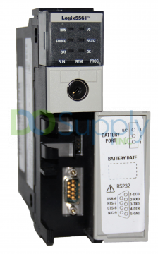
- RS232 – Recommended Standard 232 can be used for things such as monitors and CNCs. It is a point to point system that can go up to 15 meters in length with data transfer of 9600 bps. Data is transmitted in binary code.
- RS422 – Recommended Standard 424 is like RS232 but only allows one transmitting device with up to 10 receiving devices. Transfer speeds can vary depending on distance with speeds as low as 10kbps over longer ranges such as 1200 meters and up to 10 Mbps in shorter ranges of around 10 meters.
- RS485 – Industry Standard 485 is used across many industries and is the preferred standard for many. This is because of its ability to use 32-line drivers and 32 receivers. On short ranges of around 10 meters data transfer can reach 10 Mbps and it can be either half duplex with two contacts or full duplex with four.
DH +
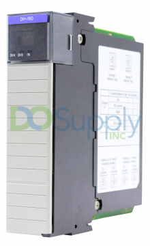
DH + is known as part of the Data Highway Protocols developed by Allen-Bradley. They are part of a local area network (LAN) solution to support remote programming and messaging between computers and programmable controllers on factory floor applications. The Data Highway Plus allows the sending of directions to various PLCs that control automation functions. It does so through the sending of message packets containing commands.
On the header of each message is a byte to indicate the source of the message, its destination and what commands are to be executed. The answer to the command is then sent back in packet form and contains a header with source, destination, and summons in the form of bytes. These two communications are managed and coordinated by a transaction code. Transaction codes will contain the reaction to the summon for the task it was called to answer.
The DH+ protocol supports 64 nodes. It can reach data transfer speeds of up to 230 Kbps. Nodes located on the network can transmit messages over cable with a token-passing protocol. In this scheme, messages can be transmitted only by nodes holding tokens. If the node is in possession of the token, it is considered the server. Once all messages have been sent or a pre-set token hold time is exceeded, the token is automatically passed to the node with the next highest address.
This continues until the token returns to the node with the lowest address and the cycle repeats. In DH+, various interface modules can control network access locally. In this way, if there is a fault in another module, the rest of the modules can still communicate with the network. This concept of a “floating server” node does not require the server to poll each node for permission to transmit. The result is a more efficient system and a network that has less overhead per transaction.
Data Highway Plus operates at 57.6 kbaud and uses a portion of the Open System Interconnection (OSI) layer model including the hardware layer, the data link layer protocol and the application layer. DH+ is better for smaller networks connecting computers and runs off bus signal voltages of 8-12 volts peer-to -peer.
Like DeviceNet, DH+ uses a trunk and drop system. This allows for inclusion of devices along the network on the factory floor. The network also uses twin axle cable and all devices on the network are n the same frequency.
The DH+ protocol and network is an older Allen-Bradley protocol. However, it is still in use and widely recognized making troubleshooting and repair easier. There are also many solutions for interfacing DH+ networks with other networks due to its proven age and compatibility with other open protocols.
It is designed to support remote programming on the factory floor. While the number of devices on the network are limited to 64 devices per link, there is a wide range of supported devices that include:
- PLC-5, PLC-3, SLC
- Color Graphics Systems
- Personal Computers
- Host Computers
- Numerical Controls
- Programmable RS232 and RS 422 devices
A network also has the capacity to allow up to 99 links. This means that multiple nodes can be added to the network through multiple links. The value of this configuration is that a single terminal on the network can be accessed to program all PLCs within all links on the network.
DH 485
The DH485 communication protocol was designed to allow factory floor information sharing. By using this network, application programs can:
- Monitor processes and device parameters
- Signal faults and alarms
- Conduct data acquisition
- Perform control functions
- Upload/Download PLC programs over the network from any available computer.
DH485 is part of the Data Highway protocol group. It is like DH+ in many ways. First, it shares the same token-passing scheme of a “floating Server” where messages can be transmitted only by nodes holding tokens. It is also designed for serial links and uses the same three open protocol layers of OSI that DH+ uses.
There are several distinctions between DH485 and DH+:
- DH485 is designed specifically for shop floor applications and has a shorter range (up to 1219 meters) and fewer nodes.
- DH485 only supports 32 nodes and runs at a data rate of 19 Kbps. These nodes can all communicate peer-to-peer using the token-transfer scheme.
- DH485 is designed as a protocol for a serial network and unlike DH+ runs on RS485 media. To allow DH485 to be seen by other RS serial media requires a converter.
Profibus
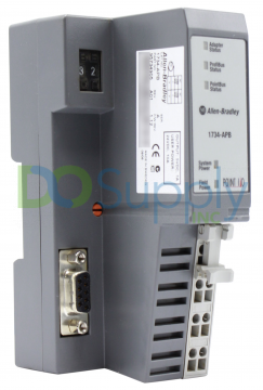
Profibus (derived from process field bus) is a serial communication protocol used in factory automation. It is used to link various automation systems with controllers and factory floor devices such as sensors, actuators, and encoders. The information is exchanged using a single bus cable. Profibus is also a smart field-bus technology that can do more than send and receive automation messages. It is capable of self-diagnosis and connection diagnosis as well.
Profibus uses three layers of the OSI Network:
- The first layer used is the application layer. Here, a variety of message types can be handled such as cyclic data, acyclic data, exchange, diagnosis, alarm handling and isochronous messaging.
- The second layer is the data link layer. Profibus uses both server/client and token-passing schemes. This gives the system flexibility in its data handling.
- The final layer is the physical layer. Profibus can use one of three types of media including twisted-pairs, fiber optics and for situations where chemical explosion is possible, it can use a safety enhanced system called Manchester Bus Power (MBP)
One interesting feature of Profibus is the use of profiles. These are pre-defined configurations of different functions that can be applied to specific devices and applications. It helps promote interoperability and interchangeability in devices used on the factory floor. Profiles allow these different devices from different OEM vendors to act in a standardized way.
Messages in Profibus
The Profibus message hierarchy consists of four message types. Each has an application and fixed build-up. Each begins with a header which is followed by the data. The four types of messages are:
- SD1 Contact Check
- SD2 Data Transport
- SD4 Token
- SC Short answer
For access to the network, server stations are the only ones allowed to send messages on their own. These include communications to devices such as PLCs and PCs. Client stations can only send with permission of a server and are usually dedicated to discrete functions such as controlling remote I/Os, sensors, actuators, and limits.
A Profibus network may be made up of many servers. These servers communicate with their client stations. However, Profibus’ unique combination of message schemes allows token sharing between server stations to facilitate communication at high-levels.
Profibus Variations
Two Profibus variations are used in the protocol today. The first is Profibus DP (Decentralized Peripherals). This variation is used in automation to operate sensors and actuators with a centralized controller and is the most common of the two variants. This variant also has three sub-variants with increasing hierarchies of features, DP-V0, DP-V1, DP-V2.
The second variation of Profibus is Profibus PA (Process Automation). It is used in high volume process automation environments and standardizes how measured data is sent. Profibus PA is also specifically designed for use in potentially explosive environments.
Specification Differences Between Profibus DP and Profibus PA
Profibus DP is one of the fastest data transfer protocols in use in automation. It has a data transmission speed of 9.6-12 Mbps with data transfer rates of up to 246 bytes each for input and output. Cable length can range from 100 meters with a corresponding drop-in baud rate up to a max of 1200 meters. It uses a trunk with drop deployment to allow additional devices to be added as needed. It can also host up to 32 devices per segment up to 126 using 4 repeaters.
Because of its specific safety enhanced design, Profibus PA has some differences to the DP version. First, it uses IEC 61158-2 physical layer media compared to RS485 used in DP. It can also host 32 devices but requires a practical limit of 0.50 amps divided by current used per device. Profibus also uses trunk and branching and has a cable length max of 1900 meters with a transmission rate of 21.25 Kbps.
Advantages of Using Profibus
As factory automation increases, Profibus has kept pace with the needs and changes. Because of this, it has many advantages for deployment:
- The single bus allows for connection of all levels of plant operation
- It is intrinsically safe
- It has diagnostic capability for both system and connection
- The use of profiles allows it to be interchangeable with other technologies.
- It is easy to troubleshoot
- It has a fast configuration time
- Wiring costs are lower compared to other networks
- Interoperability allows the connection of disparate devices
ASCII
ASCII stands for American Standard Code for Information Interchange. It is a data transmission code for electronic devices where ASCII codes represent text in computers, telecommunication, and other devices. As a communication protocol, it is question and answer mode that uses the ASCII character table to send commands to various devices. These devices, also using ASCII codes, send back responses.
ASCII is a serial communication protocol that was originally developed for electric typewriters. However, with the arrival of the PC, it was found to be a useful application for sending binary code of 128 different symbols. Because computers use binary code in 8-bit groups that contain 7 information bits and one parity bit for error checking or special characters. The code was later extended to 256 bits and is the accepted standard for PCs.
Sending and Receiving Data in ASCII
ASCII was originally designed to work with RS485 bus systems. As a result, any commands sent to a connected device must include the device address unless they are commands specifically designed to be sent to all devices on the network.
Commands are created using the ASCII character list to tell the device what it is required to do. This can also be followed by a command for CHECKSUM. This tells the device that all commands must have CHECKSUM to allow for the checking for corruption of the data string. If a command is sent without the CHECKSUM request, the command will be ignored. Responses will also begin with an address that states the device address in hexadecimals. The responses are also predetermined in the ASCII character list.
Modbus
Modbus is a communication protocol that transmits information over a serial bus line. The requesting device is called the Modbus Server and the supplying device units are the Modbus clients. In standard Modbus networks there can be up to 247 clients for a single server. Because it is an open protocol, it is a commonly used system in factory automation.
Data in a Modbus system is sent in binary code as a voltage. Zeroes are represented by positive voltage while ones are represented by negative voltage. There are for data types stored in different tables depending on response.
- Discrete Inputs
- Coils Inputs
- Input Registers (Data)
- Holding Registers (Output Data)
Sending and Receiving Messages
The Modbus Server makes a request to a client device using an addressed message that instructs the action to be performed. The request may instruct the device to read holding registers or write to Input Registers. It will also include how many registers the device is to read. There will also be a code for the client to validate the message before performing the task.
In response, the client device echoes the function code in the original request and includes the data from the task it was instructed to perform. It is also possible to report an error in the response code as well.
There are many different Modbus variations. But for this discussion, we will cover ASCII and RTU mode. Modbus networks can be set up to communicate using ASCII characters. In this mode, eight-bit bytes are sent as two ASCII characters. This allows time intervals of one second before triggering an error. The messages are coded in Hexadecimal ASCII and use Longitudinal Redundancy Checks (LRC) for errors.
In Remote Terminal Unit (RTU) mode, the eight-bit bytes contain hexadecimal characters that consist of two four bit hexadecimal. The larger character set means better data for the same level of signal. The data is sent in RTU Mode as a continuous stream. The messages use Cyclical Redundancy Checks (CRC) for error checking.
Communication Media
Both the RTU and ASCII mode of protocol utilize RS485 single cable drops. The only node allowed to initiate a command is the server. All other component devices are clients. Some variant Modbus protocols may use Ethernet. In these cases, it is possible that all devices can act as the server, but this is not common.
There are many devices such as gateways, converters and modems that can be used with Modbus. It is also possible to develop communication over wired, wireless, SMS and General Packet Radio Service (GPRS) to increase flexibility of deployment.
Advantages of Modbus
- Open Protocol – As an open protocol, Modbus allows companies to use it over a wide range of equipment.
- Simplicity – Its simple message structure allows automation for companies not looking or needing more extensive data capture and manipulation.
- Scalability – Modbus Servers can be dedicated servers to allow for monitoring of different device types. It is also possible to find Servers that do more than client device communication, enhancing any scale efforts and improving flexibility within the system.
As automation continues to grow in manufacturing, new communication protocols will emerge. But many of the ones listed here have been in service for decades and have adapted and evolved into powerful systems fully capable of managing the communication between complex devices in an equally complex environment. The key to any communication protocol will be the assessment of individual needs that include current system constraints, future growth, and the emergence of new and even faster devices communication needs.
DO Supply Inc. makes no representations as to the completeness, validity, correctness, suitability, or accuracy of any information on this website and will not be liable for any delays, omissions, or errors in this information or any losses, injuries, or damages arising from its display or use. All the information on this website is provided on an "as-is" basis. It is the reader's responsibility to verify their own facts.