How Automation Systems Stay Stable Even When Communication Isn’t
Modern industrial facilities do not stop when the network drops. A refinery keeps processing crude oil. A water treatment plant keeps dosing chemicals. A conveyor line keeps moving parts through assembly stages. This stability is not accidental; it is the result of deliberate engineering decisions built into every layer of automation systems, from the controller firmware to the field instrument logic. Communication failure is not an edge case in industrial automation. It is a known, expected condition that every well-designed system must handle without losing process stability, safety state, or data integrity.
This article breaks down the exact mechanisms, hardware, and protocol-level details that keep automation systems stable when communication degrades or fails.
Why Communication Failure Is Inevitable in Industrial Environments?
Industrial environments are electrically hostile. Variable-frequency drives inject high-frequency noise into power lines. High-voltage switchgear generates radiated electromagnetic interference during switching transients. Ground loops develop across long cable runs connecting field instruments to marshaling panels hundreds of meters away. Welding operations, motor starts, and transformer energization all create voltage spikes that can corrupt data packets in transit.
Even in facilities with well-managed cable routing and shielding practices, network failures occur. Managed switches develop port faults. Fiber-optic cables are damaged during maintenance. EtherNet/IP CIP connections drop when a device’s CPU becomes temporarily overloaded. PROFIBUS segments lose communication when a single device on the daisy chain develops a termination fault. Wireless I/O links experience packet loss during periods of radio-frequency congestion.
Controller-Level Stability: Fault Mode Configuration
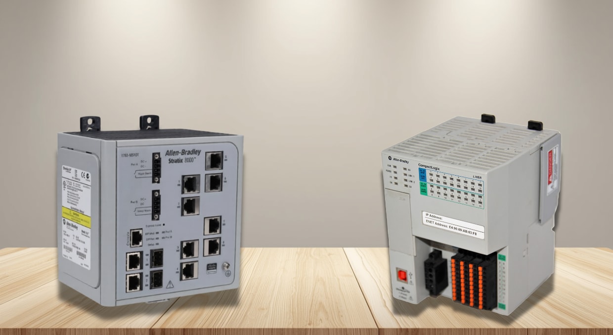
The first and most critical line of defense against communication failure is the controller’s configured response to I/O communication loss. In Rockwell Automation’s ControlLogix and CompactLogix platforms, every I/O module connection is configured with an explicit Connection Fault Mode, the instruction set to be executed by the module if its communication connection to the controller is lost.
There are three standard fault mode behaviors for each output module:
Hold Last State
The output module retains the last commanded output values when the connection drops. A valve that was commanded open stays open. A pump that was running stays running. This behavior is appropriate for processes in which the last control action represents a stable operating condition, for example, a flow control loop in which the valve position was at a steady setpoint before the fault.
Fault Value
The output module drives each output channel to a pre-configured value when the connection is lost. This value is set by the engineer during I/O module configuration and is stored in the module’s non-volatile memory, not in the controller. The module drives this value independently, without any controller involvement. This means the module continues to hold the process at a defined safe state even if the controller itself has faulted and cannot communicate at all.
Turn Off
All outputs are de-energized on connection loss. This is appropriate for fail-safe applications where the safe condition is a de-energized state, for example, a heating element that must turn off if supervision is lost.
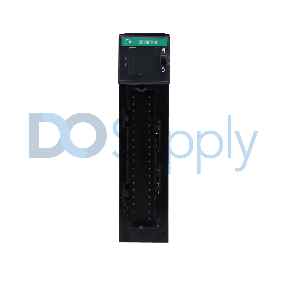
The critical engineering insight here is that these fault-mode behaviors execute entirely within the I/O module hardware, not on the controller CPU. When a ControlLogix 1756-OB16I digital output module loses its CIP connection, it does not wait for the controller to instruct it. It reads its stored fault configuration from onboard memory and executes it immediately, typically within one communication watchdog timeout period, which is configurable down to 100 milliseconds. This hardware-level autonomy is what makes the output behavior deterministic in the presence of communication failure.
Protocol-Level Stability: Watchdog Timers and Connection Supervision
EtherNet/IP, the dominant industrial Ethernet protocol used in Allen-Bradley automation systems, uses a Requested Packet Interval (RPI) and an associated connection watchdog to supervise every I/O connection. The RPI defines how frequently the controller expects to receive updated data from a device; values typically range from 2 milliseconds for high-speed I/O to 100 milliseconds for slower process instrumentation.
Every Ethernet/IP I/O connection has a watchdog timeout equal to a defined multiple of the RPI, typically 4× to 10× the RPI value. If the controller does not receive a valid packet from the device within the watchdog timeout period, the connection is declared faulted. The device simultaneously runs its own side of the watchdog; if it does not hear from the controller within the timeout, it independently transitions its outputs to their configured fault state.
This bidirectional watchdog supervision means that both sides of a communication link within the automation systems independently detect and respond to failure; neither side depends on receiving a positive “fault” notification from the other. In a network partition where packets are simply lost rather than a clean connection teardown occurring, this watchdog architecture ensures that both the controller and the device reach a defined safe state within a bounded time window, regardless of how the failure occurred.
PROFIBUS DP uses an equivalent mechanism called the watchdog control, where each slave device is configured with a watchdog time during parameterization. If the slave does not receive a valid data exchange telegram from the master within the watchdog time, it autonomously transitions its outputs to a safe state, typically zero or the last valid value, depending on the GSD file configuration of the specific device.
Redundancy Architectures: Eliminating Single Points of Communication Failure
For processes where even a brief communication interruption is unacceptable, automation systems are designed with redundant communication paths that eliminate single points of failure at the physical and protocol layers.
Redundant Controller Platforms
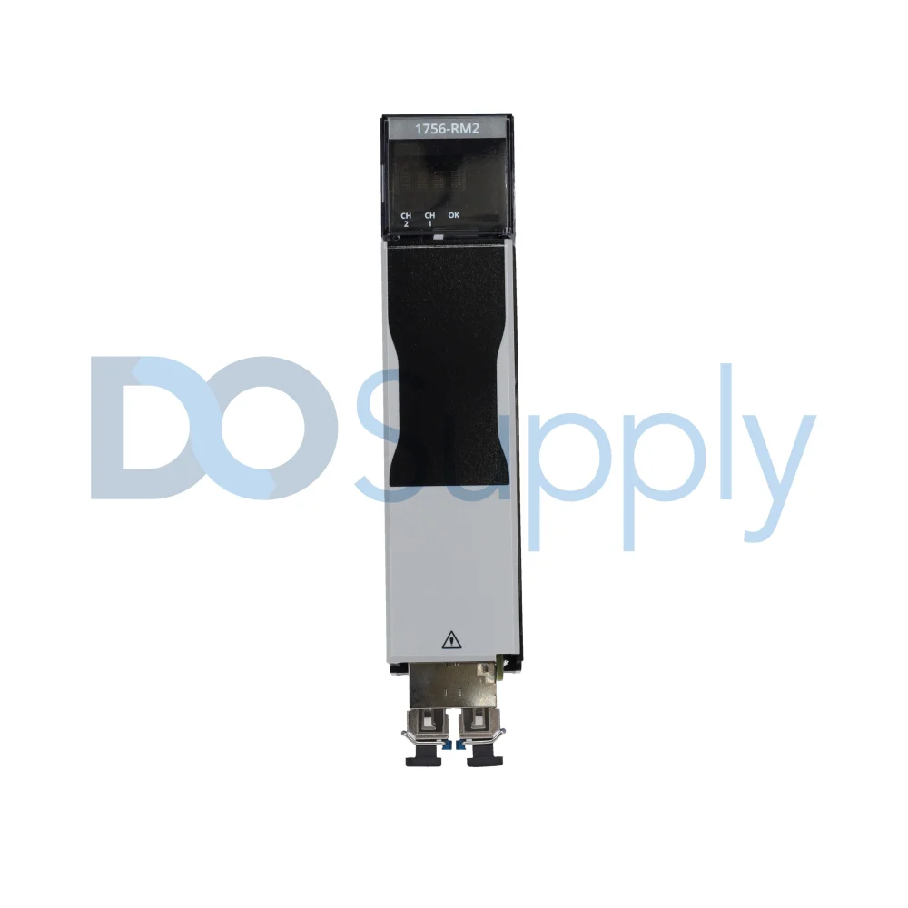
Rockwell’s ControlLogix with redundancy (using the 1756-RM2 redundancy module pair) maintains two chassis operating in lockstep: a primary and a secondary. The primary chassis executes the control program and maintains all I/O connections. The secondary chassis stays synchronized with the primary via a dedicated high-speed fiber-optic redundancy link that continuously transfers controller state, program data, tag values, and I/O image tables. If the primary chassis loses power, a CPU fault occurs, or its network connection is lost, the secondary chassis assumes control in under 30 milliseconds for most application types. From the I/O network’s perspective in the automation systems, the switchover is transparent; the new primary immediately takes ownership of all existing CIP I/O connections without requiring a connection teardown and re-establishment cycle.
Ring Topology Ethernet/IP Networks
Device Level Ring (DLR) is a resilience protocol embedded in Ethernet/IP that allows devices to be connected in a physical ring topology. Under normal operation, DLR intentionally blocks one link in the ring to prevent loops, creating a logical linear network. When a cable or switch failure occurs anywhere in the ring, DLR’s ring supervisor detects the topology change within 3 milliseconds and reconfigures the ring to route traffic around the fault, restoring communication to all devices using the surviving cable path.
PROFIBUS Redundant Masters
In high-availability PROFIBUS DP systems, dual master stations are deployed in a primary/backup configuration. The backup master operates in passive monitoring mode, receiving all telegrams on the bus and tracking the current state of every slave. If the primary master fails, the backup transitions to active mode. It resumes data exchange with all slaves without requiring re-parameterization, because it already holds a complete current snapshot of the network state.
Controller Autonomous Execution: The Heartbeat of Stability
One of the most important stability mechanisms in automation systems is the controller scan cycle, which operates independently of all external communication. A ControlLogix or CompactLogix controller running a continuous task executes its control program on a deterministic scan cycle regardless of what is happening on any network connection. The controller does not pause its logic execution when an I/O connection faults. It does not wait for a device to recover before continuing to process the program scan.
Instead, the controller maintains a connection status tag for every I/O module, for example, Local:2:I.ConnectionFaulted for a module in slot 2 of the local chassis. When communication to that module is lost, this status bit is set to 1 within one watchdog timeout period. The control program can read this status bit in ladder logic and execute alternate control paths, switching from automatic to manual mode, driving a backup output, generating an alarm, or placing the affected loop in a defined hold condition. This conditional logic, pre-programmed by the engineer, allows the controller to continue meaningful control actions even when field device communication is degraded.
Data Integrity Under Communication Stress: Buffering and Store-and-Forward
Communication instability not only affects control outputs but also disrupts data continuity. When a network link between a field controller and a SCADA historian drops, process data can be lost if no buffering mechanism is in place. Modern automation systems address this by using store-and-forward data buffering, implemented either in the controller, at an edge gateway, or in a dedicated historian agent running at the site level.
At the controller level, Logix controllers support Produced and Consumed Tags that allow controllers to exchange data directly over EtherNet/IP without SCADA involvement. If the SCADA server loses connectivity, controller-to-controller data exchange continues uninterrupted, and process interlocks, permissive signals, and shared setpoints between controllers remain active because they operate on a direct CIP connection that does not route through the SCADA server.
Final Thoughts
In conclusion, stability in automation systems is not achieved by preventing all possible failures. Networks fail. Cables get damaged. Switches drop ports. Wireless links go down during storms. Stability is the result of engineering every layer of the system to behave predictably, safely, and autonomously when failures occur, so that the physical process remains under control even when the communication infrastructure holding it together temporarily fails. If you would like to read on, we have a blog post here that goes over what happens when a PLC misses a packet.
Whether you are bolstering your factory’s industrial network or spec’ing a new automated process, make DO Supply your trusted supplier for all things automation. We carry everything from PLCs to managed switches, drives, and safety modules from industry-leading brands. On top of that, all of our products are tested before they even leave the door to ensure you get a working part you can trust. Give us a call today, and our sales team can help you find just what you need to take your automation solution to the next level.
DO Supply Inc. makes no representations as to the completeness, validity, correctness, suitability, or accuracy of any information on this website and will not be liable for any delays, omissions, or errors in this information or any losses, injuries, or damages arising from its display or use. All the information on this website is provided on an "as-is" basis. It is the reader's responsibility to verify their own facts.