
2711C-T6T
This HMI terminal is designed with a 320 x 240 pixel resolution on a 6-inch display, ensuring clear visibility for user interactions. It includes a USB port and an SD card port for robust data managem
In Stock Ships Today
4.7
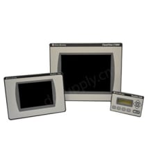
The PanelView Components are graphics terminals and panel-mounted display screens that are designed and manufactured by Allen-Bradley. The component terminals from PanelView Components series are user interface devices that are used for monitoring and controlling applications. These Components are available with keypads or touchscreens for operator input. The Components’ programming and applications are created by using the PanelBuilder 32 software. The program should be downloaded from the terminal interface. The Components are equipped with USB host ports. The terminals can be configured by using the runtime interface. The components of the Components are the keypad which includes functional keys, cursor control keys, and the numerical keys. They also have power units, RS-422 and RS-485 ports, USB ports, diagnostic status indicators, mounting slots, Ethernet ports, and replaceable real-time clock batteries.
The Components’ settings can be adjusted by using the PanelView Explorer window. The settings can be viewed and edited for the connected PanelView component terminals according to their needs. The operators can adjust the brightness and contrast, configure the screen saver settings, reset the terminal, view system information, change the language, calibrate the screen, and change the password of the system administrator easily on these Components. All of the components are certified with the c-UL-us, CE, EAC, RCM, and KC standards. The PanelView Display Components are equipped with SD memory cards, USB drives, and backup batteries. These Components can be replaced and upgraded if needed. The system information for the connected terminal can be viewed on the Components’ screens. The Components can be connected directly to the PowerFlex 4 drives and they are highly compatible with the Allen-Bradley MicroLogix and Micro 800 controllers. The Components feature secured programming, Unicode language support, alarm messages, and various security features.
Browse available units in our catalog of Panelview Component.
This HMI terminal is designed with a 320 x 240 pixel resolution on a 6-inch display, ensuring clear visibility for user interactions. It includes a USB port and an SD card port for robust data managem

Allen Bradley PanelView Component, C1000 Model, 10 in., Color (TFT) 10 Display

Allen Bradley PanelView Component, C400 Model, 4 in., Color (TFT) Display

Allen Bradley PANELVIEW COMP C600 GRAPHIC TERMINAL Touchscreen Model Color Display Operator Inteface HMI

Allen Bradley PanelView Component, C600 Model, 6 in., Monochrome Display

Allen Bradley PanelView Component, C300 Model, 3 in., Monochrome Display

Allen Bradley PanelView Component, C200 Model, 2 in., Monochrome Display

Allen Bradley PanelView Component, C300 Model, 3 in., Monochrome Display

Allen Bradley PanelView Component, C200 Model, 2 in., Monochrome Display
The Component series is an Allen-Bradley Panelview series of 9 devices. The Panelview Component series units provide operator interfaces and they are used for device control and monitoring. The HMI applications feature web applications, and the Component devices support desktop connectivity. The Component series comprises terminals that are built to provide visualization and control for the low-end applications that are built to use Ethernet communication ports. The PanelView Component series terminals are panel-mounted displays that offer the keypad or touchscreen input options. The Component graphic terminals come with USB ports that support device communication with terminals using TCP/IP. The USB ports support connection to a computer for allowing the users to use a supported browser and to connect to the terminals. Note that before connecting the Component terminals to computers by using the USB ports, the users must install the Allen-Bradley PanelView USB remotes on their devices.
The Component series features units known as C600 and C1000 units that come with Ethernet interfaces. The Ethernet interface supports static IP addresses and the dynamic host configuration protocol. The PanelView Component control interface also features USB host ports. The users can power the USB peripherals directly from the PanelView Component terminals. The Component terminals can be configured from the design-time or the run-time user interface. If the users configure the terminals with the design-time interface, they will need computer browsers to be connected to the terminals’ web service. If the users are configuring the terminals with the run-time user interface, they must utilize the configuration screens on the terminals. The Component series supports SD memory cards that can be inserted on the C600 and the C1000 PanelView Component terminals.
If the terminal is not starting up correctly always check for adequate power first. Inadequate power can cause a variety of unpredictable behavior. Simply verify the terminal's power requirement in the specifications table. It is also good practice to determine whether there have been any changes since the last startup. Determine what these are to see if they can be reversed.
If you continue have start-up issues, observe the splash screen for state messages and for the status or error codes.
| Message | Code | State |
| Failed RAM | 6C | Fatal |
| Stuck Key | 31 | Fatal |
| Stuck Touch | 3A | Fatal |
| Message | Code | State |
| Load Firmware Image into RAM | 1E | Update |
| Write Firmware Image into Flash | A5 | Update |
| Complete & Successful Firmware Installation | OK | Update |
| Invalid or Missing Firmware Image | 0A | Fatal |
| Firmware Image Validation (CRC/Format) Failure | 1E | Fatal |
| Firmware Image Compatibility Failure | 1F | Fatal |
| Firmware Write-to-Flash Error | A5 | Fatal |
| Firmware Read-after-Write Verify | D2 | Fatal |
| Message | Code | State |
| Operating System Start-Up | GO | Boot |
| Operating System Initialize | I1...J0 | Init |
| Boot Loader Connects to PC via USB Device | 0A | AutoTest |
| Boot Loader Jumps to Operating System | FF | AutoTest |
| Boot Loader Loads Firmware Image into RAM | E6 | AutoTest |
| Application Registration and Initialize | N1...N3 | Init |
| Application Load and Execute | N4...N6 | Load |
Please note: Power-on self-test errors are fatal and likely caused by failed hardware. If the fatal error occurred during firmware installation and loading the terminal is likely recoverable. In this case, try installing the correct firmware.
Power indicators are located on the front of the C400 terminal, they communicate the system status. The green LED indicator lets the operator know the system is running and the display is on, whereas the red LED indicator shows that the system is running but the display is in screen saver mode.
There are also two indicators on the back of the terminal, which help the operator identify operating issues. The Green Comm indicator reflects communication issues while the red Fault indicator reflects hardware faults. The table below helps identify potential problems if the terminal fails during startup.
| Fault Indicator (Red) | Comm Indicator (Green) | Meaning | Action |
| Possibly Recoverable | |||
| Blinking | On | Windows CE OS firmware failed/missing | Reload Firmware |
| Blinking | Off | Last firmware download failed | Reload Firmware |
| Blinking | Blinking | EBC boot loader firmware failed/missing | Reload Firmware |
| Fatal Errors | |||
| On | Off | Fatal hardware error | Replace Terminal |
| On | Blinking | Fatal display hardware error | Replace Terminal |
Returning the terminal to out-of-the-box condition can help the system recover from application misbehavior. This procedure will also restore your terminal if you have set terminal security and forgotten your password.
If the terminal does not recognize the keyboard, simply restart the terminal and wait for the boot screen to display code N1 and repeat step 2. You will know that the keyboard has not been recognized if the terminal boots normally, displaying the configuration screen or startup application.
When you return the terminal to its factory settings or out-of-box condition, the current firmware will remain on the terminal. This is the case whether or not you have upgraded the firmware.
When the terminal resets the file system is formatted and removes applications, logs, user-installed fonts, objects, graphics, and recipes. Additionally, terminal configuration parameters return to their default settings.
Here at DO Supply, we offer repair services for your Allen-Bradley products, such as the Allen-Bradley Component Terminal. Please click here for more information or to request a quote.