
1761-NET-ENI
This interface module has a backplane current requirement of 50 mA at 24V and can handle an inrush current up to 200 mA. It supports both DIN rail and panel mounting options for versatile installation
In Stock Ships Today
4.9
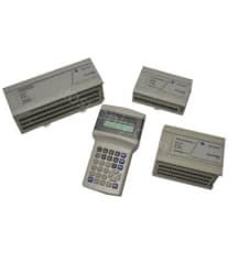
The Allen-Bradley MicroLogix 1000 Programmable Logic Controller (PLC) system is a platform for small-scale industrial applications. These PLCs come in 2 variants, with 16 or 32 I/Os whereby the users can select models with a different number of inputs and outputs. MicroLogix 1000 controllers come with AC or DC power supplies and the digital inputs can be AC or DC rated. Outputs from these PLCs can be relay outputs covering both AC and DC loads, Triac outputs that are able to work with AC loads, or MOSFET outputs dedicated to DC loads. The MicroLogix 1000 PLCs are designed using reliable technology, they have several programming options, and they have respectable execution speed for programming instructions. Therefore, they are widely installed in industrial automation applications and they can often be seen in industrial plants and machines.
The Allen-Bradley MicroLogix 1000 PLCs are installed in various applications including building controls, custom machinery, cutting tools, furnaces, burners, dryers, civil engineering, specialized industrial machinery, food processing, material fluid handling, metalworking, and packaging machinery applications. These PLCs are programmed with the general ladder-programming technique, and users can use the MicroLogix 1000 Programming Software, Advanced Programming Software, and the Hand-Held Programmer for instruction input. The supported instruction package includes timers, sample bits, shift registers, counters, sequencers, and high-speed counters. When creating applications, the standard option for adjustable DC input filters on MicroLogix 1000 devices can be very useful. There is also an RS-232 connector on the device for computer connections.
Browse available units in our catalog of MicroLogix 1000.
This interface module has a backplane current requirement of 50 mA at 24V and can handle an inrush current up to 200 mA. It supports both DIN rail and panel mounting options for versatile installation

Designed for efficiency, this interface converter supports multidrop networks and interfaces with DH-485 applications. It manages a maximum of 32 nodes in a single network. The 1761-NET-AIC draws a cu

This unit operates with a power supply voltage between 85 and 264 volts AC at a frequency of 47-63 Hz. The controller’s memory is based on EEPROM technology, holding around 1K, translating to approxim

This network cable features 8-pin Mini DIN to 9-pin D-Shell connectors for versatile connectivity options. It is compatible with Class 1 Division 2 applications when paired with Series C or later cabl

Allen Bradley-PLC 32 I/O MICROLOGIC-1000 100/120VAC 50-60HZ AB

Allen Bradley-PLC MODULE 16 I/O MICROLOGIX 1000 AB

Allen Bradley-PLC 16 I/O AC INPUT RELAY AB

Allen Bradley-PLC 16I/O MICROLOGIX 1000 W/ 10 INPUTS 6 RELAY AB

Allen Bradley-PLC MICROLOGIX 32 I/O 20 I DC/12 OR DC/2 AB

Allen Bradley-PLC 32 I/O DC/10 O DC/DCV MICROLOGIX 1000 AB
Before power is applied and communication between a connected programming device is established, the only form of communication between yourself and your MicroLogix 1000 controller is through LEDs. See the tables below to interpret your LED Status.
When power is connected, only the power LED turns on and remains on. This is part of the normal powerup series. When the MicroLogix 1000 controller is placed in REM Run mode, the run LED also turns on and remains on, as described below. If a force is present, the force LED is on as well.
Consult the following text references to understand the status of your MicroLogix 1000's LED indicators: N means the LED is OFF. O means the LED is ON. F means the LED is Flashing. X means the status of the LED Does Not Matter.
| LED Indicator | Powered Up | In RRUN Mode |
| Power | On | On |
| Run | Off | On |
| Fault | Off | Off |
| Force | Off | N/A |
If an error exists within the MicroLogix 1000 controller, the controller LEDs illuminate as described in the following tables.
| LED Display | Error | Possible Cause | Suggested Action | |
|
Power Run Fault Force |
OFF OFF OFF OFF |
No input power, or power supply error |
No line power |
Verify proper line voltage and connections to the controller. |
| No input power, or power supply error | Power supply overload | This problem can occur occasionally if power supply is overloaded when output loading and temperature varies | ||
| LED Display | Error | Possible Cause | Suggested Action | |
|
Power Run Fault Force |
ON OFF ON OFF |
Hardware faulting |
1. Processor Memory Error 2. Loosened wiring |
1. Cycle unit power. Contact your local Allen-Bradley representative if the error persists. 2. Check connections to the MicroLogix 1000 controller |
| LED Display | Error | Possible Cause | Suggested Action | |
|
Power Run Fault Force |
ON OFF FLASH N/A |
Application | Hardware/Software Major Fault detected |
1. Monitor Status File Word S:6 for major error code. 2. Remove the hardware or software condition causing the fault. 3. Press F10 to clear the fault. 4. Attempt a MicroLogix 1000 controller REM Run mode entry. If unsuccessful, repeat recommended action steps above. |
Refer to the following error recovery schematic to help you diagnose software and hardware problems in the MicroLogix 1000 controller. The schematic provides common questions you might ask to help troubleshoot the system.
While a program is executing, a fault may occur within the operating system or your program. When a fault occurs, you have several ways to determine what the fault is and how to correct it. This section describes how to clear faults and gives a list of possible advisory messages with recommended corrective actions.
You can automatically clear a fault when cycling power to the MicroLogix 1000 controller by setting either one or both of the following status bits in the status file:
Note: You can declare your own application-specific major fault by designating your own unique value to S:6 and then setting bit S:1/13 to prevent reusing system defined codes. The recommended values for user defined faults is FF0 to FF0F
The occurrence of recoverable or non-recoverable user faults causes file 3 to be executed. If the fault is recoverable, the sub-routine can be used to correct the problem and clear the fault bit S:1/13. The MicroLogix 1000 controller then continues in the REM Run mode. The subroutine does not execute for non-user faults.
This sections describes fault messages that can occur during operation of the MicroLogix 1000 programmable controllers. Each table lists the error code description, the probable cause, and the recommended action to solve the error.
| Error Code (Hex) | Advisory Message | Description | Recommended Action to Solve |
| 0001 | DEFAULT PROGRAM LOADED | The default program is loaded to the computer memory. This occurs on power-up if the power down occurred during a download, or if the user program is corrupt at power up, the default program is loaded. | Re-download the program and enter the REM Run mode. |
| 0002 | UNEXPECTED RESET | The controller was unexpectedly reset due to a noisy evnironmentt or internal hardware failure. If the user program downloaded to the controller is valid, the initial data downloaded with the program is used. The Retentive Data Lost Bit (S:5/8) is set. If the user program is invalid, the default program is loaded. | Refer to proper grounding guidelines. |
| 0003 | EEPROM MEMORY IS CORRUPT | While power cycling to your MicroLogix 1000 controller, a noise problem may have occurred. Your program may be valid, but retentive data will be lost. | Try cycling power again. |
| 0004 | RUNTIME MEMORY INTEGRITY ERROR | During the time the MicroLogix 1000 was in RUN mode or any test mode, the ROM or RAM became corrupt. If the user program is valid, the program and initial data downloaded to the controller is used and the Retentive Data Lost Bit (S:5/8) is set. If the user program is invalid, error 0003 takes place. | Cycle power on your MicroLogix 1000 unit. Download your program and reinitialize any necessary data. Start up your system. |
| 0005 | RETENTIVE DATA HAS BEEN LOST | Data files (input, output, timer, counter, integer, binary, control, and status) are corrupt. | Cycle the power on your MicroLogix 1000 unit. Download your program, and reinitialize any necessary data. Start your system. |
| 0008 | FATAL INTERNAL SOFTWARE ERROR | The MicroLogix 1000 controller software has detected an invalid condition within the hardware or software after completing power-up processing (once the first 2 seconds of operation have been completed). | Cycle the power on your unit. Download your program and reinitialize any necessary data. Start your system. |
| 0009 | FATAL INTERNAL HARDWARE ERROR | The MicroLogix 1000 controller software has detected an invalid condition within the hardware during start-up processing (once the first 2 seconds of operation have been completed). | Cycle the power on your unit. Download your program and reinitialize any necessary data. Start your system. |
| 0010 | INCOMPATIBLE PROCESSOR | The program downloaded is not configured for the MicroLogix 1000 controller. | If you want to use a micro controller with the program, configure your controller with your programming software. (choose Bul. 1761). |
| 0016 | STARTUP PROTECTION AFTER POWER LOSS S:1/9 IS SET | The system powered up in the REM Run mode. Bit S:1/13 is set and the user-fault routine is run before beginning the first scan of the program. | Either reset bit S:1/9 if this is consistent with your application requirements, and change the mode back to REM Run, or clear S:1/13, the major fault bit. |
| 0018 | USER PROGRAM IS INCOMPATIBLE WITH OPERATING SYSTEM | An incompatible program was downloaded. Either the program does not have the correct number of files, or it does not have the correct size data files. The default program is downloaded. | Check the configuration and make sure the correct processor is selected. If you want to use a MicroLogix 1000 with the program, reconfigure your controller with your programming software. (choose Bul. 1761). |
| 0020 | MINOR EFFOR AT END OF SCAN, SEE S:5 | A minor fault bit (0-7) in S:5 was set at the end of the scan. | Enter the status file display and clear the fault, then return to the REM Run mode. |
| 0022 | WATCHDOG TIMER EXPIRED, SEE S:3 | The program scan time exceeded the watchdog timeout value (S:3H) | Ensure the program is caught in a loop and correct the problem, and increase the watchdog timeout value in the status file. |
| 0024 | INVALID STI INTERRUPT SETPOINT, SEE S:30 | An invalid STI interval exists (not between 0 and 255). | Set the STI interval between the values of 0 and 255. |
| 0025 | TOO MANY JSRs IN STI SUBROUTINE | There are more than 3 subroutines nested in the STI subroutine (file 5) | Correct the user program to meet the requirements and restrictions for the JSR instruction. Reload the program and enter the REM Run mode. |
| 0027 | TOO MANY JSRs IN FAULT SUBROUTINE | There are more than 3 subroutings nested in the fault routine (file 3). | Correct the user program to meet the requirements and restrictions for the JSR instruction. Reload the program and enter the REM Run mode. |
| 002A | iNDEXED ADDRESS TOO LARGE FOR FILE | The program is referencing through indexed addressing an element beyond a file boundary. | Correct the user program so that it does not go beyond file boundaries. |
| 002B | TOO MANY JSRs IN HSC | There are more than 3 subroutines nested in the high-speed counter routine (file 4). | Correct the user program to meet the requirements and restrictions for the JSR instruction. Reload the program and enter the REM Run mode. |
| 0030 | SUBROUTINE NESTING EXCEEDS LIMIT OF 8 | There are more than 8 subroutines nested in the main program file (file 2). | Correct the user program to meet the requirements and restrictions for the main program file. Reload the program and enter the REM Run mode. |
| 0031 | UNSUPPORTED INSTRUCTION DETECTED | The program contains an instruction or instructions that are not supported by the micro controller. For example, SVC or PID. | Modify the program so that all instructions are supported by the MicroLogix 1000 controller. Reload the program and enter the REM Run mode. |
| 0032 | SQO/SQC CROSSED DATA FILE BOUNDARIES | A sequencer instruction length/position parameter points past the end of a data file. | Correct the program to make sure that the length and position parameters do not point past the data file. Reload the program and begin REM Run mode. |
| 0033 | BSL/BSR/FFL/FFU/LFL/FLU CROSSED DATA FILE BOUNDARIES | The length parameter of a BSL, BSR, FFL, FFU, LFL, or LFU instruction points past the end of a data file. | Correct the program to ensure that the length parameter does not point past the data file. Reload the program and enter the REM Run mode. |
| 0034 | NEGATIVE VALUE IN TIMER PRESET OR ACCUMULATOR | A negative value was entered to a timer preset or accumulator | If the program is moving values to the accumulated or preset word of a timer, ensure these values are positive. Reload the program and enter the REM Run mode. |
| 0035 | ILLEGAL INSTRUCTION (TND) IN INTERRUPT FILE | The program contains a Temporary End (TND) instruction in file 3, 4, or 5 when it is being used as an interrupt subroutine. | Correct the program. Reload the program and enter the REM Run mode. |
| 0037 | INVALID PRESETS LOADED TO HIGH-SPEED COUNTER | Either a zero (0) or a negative high preset was entered to counter (C5:0) when the HSC was an Up counter or the high preset was lower than or equal to the low preset when the HSC was a Bidirectional counter. | Check to make sure the presets are valid. Correct the program, reload, and enter the REM Run mode. |
| 0038 | SUBROUTINE RETURN INSTRUCTION (RET) IN PROGRAM FILE 2) | A RET instruction is int he main program file (file 2). | Remove the RET instruction. Reload the program and enter the REM Run mode. |
| 0040 | OUTPUT VERIFY WRITE FAILURE | When ourputs were written and read back by the MicroLogix 1000 controller, the read failed. This may have been caused by noise. | Refer to proper grounding guidelines. Start your system. |
| 0041*** | EXTRA OUTPUT BIT(S) TURNED ON | An extra output bit was set when the Extra Output Select (S:0/8) bit in the status file was reset. For 16-point controllers this includes bits 6-15. For 32-point controllers this includes bits 12-15 | Set S:0/8 or change your application to prevent these bits from being turned on. Correct the program, reload, and enter the REM Run mode. |
***Valid for Series A-C discrete only.
Here at DO Supply, we offer repair services for your Allen-Bradley products, such as the Allen-Bradley MicroLogix 1000 Controller. Please select the Repairs tab for more information or to request a quote.