
1398-DDM-019
The Allen-Bradley 1398-DDM-019 Servo Drive has a 18 amps rms AC Input Current and a 120 Vac 1.2 kWatts; 240 Vac 2.5 kWatts Continuous Power Output.
In Stock Ships Today
4.7
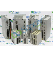
The Allen-Bradley 1398 Ultra servo drive product line is a series of single-axis digital and positioning servo drives. It comprises 2 sub-series which are the Ultra 100 and Ultra 200 series, and both of these can be managed through the Windows-based Ultra Master software. The 1398 Ultra 100 and 200 drives can be set up as indexing drives, stepper drives, velocity servo drives, or master encoder followers. Ultra 100 drives can be remotely programmed through the DeviceNet network option. The 1398 Ultra 100 and 200 drives are available in 7 power ranges and they are compatible with 4 brushless servo motor families. The 1398 Ultra 100 drives support single-phase 115 to 230 Volts AC input voltage, they include integrated logic power supplies, they can drive AC brushless motors, they support control algorithms for velocity loop bandwidth and velocity and position loops, they include a 14-bit analog-to-digital converter, and support multiple analog and digital I/Os. One RS-232/RS-485 port is included as a standard feature.
The Allen-Bradley 1398 Ultra 100 drives are available in power ratings ranging from 0.5 kilowatts to 2 kilowatts and they require a –5 to 50 degrees Celsius operating temperature range. The 1398 Ultra 200 drives support 115 to 230 Volts AC input voltage. The 75 Amps drives support both single and 3-phase input while the 150 Amps drives support only 3-phase input. Features available on the 1398 Ultra 200 drives include an internal resistive shunt, a built-in power supply, an advanced multiprocessor design, a 16-bit analog to digital converter, short circuit protection, flash memory for field upgrades, and multiple analog and digital command interfaces. The 1398 Ultra 200 drives are available in power ratings ranging from 1 to 15 kilowatts.
Browse available units in our catalog of Servo Drive 1398.
The Allen-Bradley 1398-DDM-019 Servo Drive has a 18 amps rms AC Input Current and a 120 Vac 1.2 kWatts; 240 Vac 2.5 kWatts Continuous Power Output.

The Allen-Bradley 1398-DDM-075 Servo Drive has a 16-Position Rotary DIP Address Switch and a 141-339 Volts DC Bus Voltage.

The Allen-Bradley 1398-PDM-020 Servo Drive has a 10 amps/Phase Continuous Output Current and a 32-140 F (0-50 C) Operating Temperature.

The Allen-Bradley 1398-DDM-030 Servo Drive has a 28 amps rms AC Input Current and a 32-131 F (0-55 C) Operating Temperature.

The Allen-Bradley 1398-DDM-019X Servo Drive has a 18 amps rms AC Input Current and a 120 Vac 1.2 kWatts; 240 Vac 2.5 kWatts Continuous Power Output.

The Allen-Bradley 1398-HMI-001 Servo Drive has a and a .

The Allen-Bradley 1398-PDM-030 Servo Drive has a 15 amps/Phase Continuous Output Current and a 32-140 F (0-50 C) Operating Temperature.

The Allen-Bradley 1398-DDM-009 Servo Drive has a 47-63 Hz AC Input Frequency and a 120 Vac 0.6 kWatts; 240 Vac 1.2 kWatts Continuous Power Output.

The Allen-Bradley 1398-DDM-009X Servo Drive has a 47-63 Hz AC Input Frequency and a 120 Vac 0.6 kWatts; 240 Vac 1.2 kWatts Continuous Power Output.

The Allen-Bradley 1398-DDM-019X-DN Servo Drive has a 47-63 Hz AC Input Frequency and a 120 Vac 1.2 kWatts; 240 Vac 2.5 kWatts Continuous Power Output.
Two indicators on the front panel continuously display the drive status:
A table of problems, potential causes, and appropriate responses to resolve the problem is located below.
| Problem | Error Code | Possible Causes | Response |
| Status display not lit. |
No AC power Blown power fuse(s) |
Ensure power (115/230VAC single phase or 230 VAC three phase) is applied to the drive. Check for open circuits in the AC line fuses |
|
| DC BUS LED not lit. |
No Bus power Blown power fuse(s) |
Make sure AC power is connected to the drive Check for open circuit breakers in the AC line |
|
| Motor jumps when first activated |
Motor encoder wiring error Incorrect motor selected in personality module |
Inspect motor encoder wiring. Review Figure 6.36 on page 30 to verify connection of encoder power sense signals. Choose the proper motor in ULTRA Master |
|
| Digital I/O not working correctly | 24V power supply disconnected | Ensure P5/P6 jumper settings are correct | |
| +24V Fuse Blown | E01 | F1 Blown |
The fuse on the I/O isolated +24VDC power supply has tripped. Check and replace fuse F1 if necessary. Check for short circuits on I/O or +24VDC output |
| +5V Fuse Blown | E02 | F2 Blown |
The fuse on the encoder power output for the +5VDC power supply has tripped. Check and replace fuse F2 if necessary. Check for short circuits on Encoder output signals or +5V output. Check that J4 pin9 or J5 pin9 is not connected to any external circuit. |
| Encoder Fuse Blown | E03 |
F3 Blown Bad encoder |
Check for short circuits on the motor Encoder signals and cable wiring. Check and replace fuse F3 if necessary. |
| Motor over temperature | E04 |
Motor TS+ (J2-19) and TS- (J2-20) pins open Motor thermostat will trip due to: High motor ambient temperature and/or Excessive RMS torque |
Verify TS+ (J2-19) and TS- (J2-20) connections for continuity. Lower ambient temperature. Operate inside (not above) the continuous torque rating for the ambient temperature (40° Celsius maximum). |
| IPM Fault | E05 |
Motor cables shorted Motor winding internally shorted Drive temperature running too high Operation above continuous power rating Output short circuit or overcurrent |
Ensure continuity of motor's power cable and connector. Check for short circuit on R, S, T, and Gnd windings. Check for a clogged or deffective fan. Ensure that cooling is not restricted by insufficient space around the unit. Ensure that ambient temperature is not too high (above 60° Celsius). Operate drive within the continuous power rating. Driver has a bad IPM, replace drive. |
| Channel IM line | E06 |
Bad connection Bad encoder |
Ensure continuity of the encoder cable. Ensure continuity of the IM+ and IM- wiring signals. Replace the motor or Eencoder. |
| Channel BM line | E07 |
Bad connection Bad encoder |
Ensure continuity of the encoder cable. Ensure continuity of the BM+ and BM- wiring signals. Replace the motor or encoder. |
| Channel AM line | E08 |
Bad connection Bad encoder |
Ensure continuity of the encoder cable. Ensure continuity of the AM+ and AM- wiring signals. Replace the motor or encoder. |
| Bus under voltage | E09 | Low AC line/AC input (100 V AC minimum for safe drive operation) |
Check voltage level of the incoming AC power. Check main VAC power source for glitches or drop (below 90 VAC). Install an uninterruptible power supply (UPS) on your VAC input. |
| Bus over voltage | E10 |
Excessive regeneration of power. When the drive is operated by an external mechanical power source, it may regenerate too much peak energy through the drive's power supply. The system will fault to save itself from an overload. Excessive AC voltage input Output short circuit Motor cabling wires shorted together Internal motor winding short circuit |
Change the deceleration or motion settings and/or reduce the reflected intertia of your mechanical system, or use a larger system (motor and drive). Ensure input is below 264 VAC. Inspect for short circuits Inspect for short circuits Inspect for short circuits |
| Illegal Hall State | E11 |
Incorrect phasing Bad Connections |
Check the Hall phasing Verify the Hall wiring |
| Excessive Average Current | E17 |
Excessive time at peak curent Software parameter set too low Insufficent bus voltage |
Reduce acceleration rates. Reduce duty cycle (ON/OFF) of commanded motion. Increase time permitted for motion. Use a larger drive and motor. Increase Average Current parameter to a more permissive setting. Correct the under voltage condition or intermittent AC power, or install a larger size transformer. |
| Motor over speed | E18 |
OVERSPEED parameter in the drive may be set too low for the application Motor commanded to run above overspeed setting Motor phasing is incorrect Motor encoder phasing is incorrect |
Using ULTRA Master (refer to Drive Parameters section) set Overspeed parameter to an acceptable range for the application. Reduce command from position controller or change velocity parameter in the position controller. Inspect motor phasing Inspect encoder phasing |
| Excess Following Error | E19 | Software position error limit exceeded |
Increase the feed forward gain to 100%. Increase the following error window (refer to ULTRA Master Drive Parameters section). Retune the drive to reduce the following error. Increase the slwe limit window (refer to ULTRA Master Drive Parameters). |
| Motor Encoder State Error | E20 |
Motor encoder encountered an illegal transition Bad encoder |
Replace the motor and/or encoder Use shielded cables with twisted pair wires. Route the feedback away from potential noise sources. Check the system grounds. Replace motor and/or encoder |
| Auxilary Encoder state error | E21 | Auxilary encoder encountered an illegal transition |
Use shielded cables with twisted pair wires Route the encoder cable away from potential noise sources Fauly encoder - replace the encoder Check the ground connections |
| Motor Thermal Protection Failure | E22 | Internal filter protecting the motor from overheating has tripped |
Reduce acceleration rates. Reduce duty cycle (ON/OFF) of commanded motion. Increase time permitted for motion. Use larger drive and motor. |
| IPM Thermal Protection Failure | E23 | Internal filter protecting the IPM at slow speed has tripped. | Reduce acceleration rates. Reduce duty cycle (ON/OFF) of commanded motion. Increase time permitted for motion. Use larger drive and motor. |
| Velocity Error | E24 | Velocity error exceeded specified limit and time parameters. | Increase allowable error parameters. |
| Commutation angle error | E25 | Encoder index location is inconsistent | Replace the encoder. Check encoder and motor power wiring. |
| Axis not Homed | E27 | An absolute indexing move was attempted without previously homing the axis | Home the drive before attempting an absolute indexing profile. |
| No Motor Selected | E28 | No motor was selected when the drive was enabled | Select a motor before enabling the drive |
| Motor Information Missing | E29 | Motor number is referencing a motor that is not currently in the drive |
Select a motor that is in the drive. Update the motor tables in the drive. |
| Personality EEPROM Read Error | 54 |
Personality EEPROM is not compatible with the drive firmware Hardware is malfunctioning. |
Upgrade firmware |
| Personality EEPROM | 83 | Personality EEPROM unable to be used with an indexing drive | Use a non-indexing drive |
Here at DO Supply, we offer repair services for your Allen-Bradley products, such as the Allen-Bradley Servo Drive 1398. Please select the Repairs tab for more information or to request a quote.