Relay Output vs Solid State Output Modules
In designing industrial automation systems, half of the challenge is how you wish to control a system, and the other half is in how to connect the system’s components together. Specifying input, output, and communication methods can be a huge undertaking, as all other devices up- and downstream have to be both compatible with, and reliable when using, your selected technologies. To aid in your selection of PLC connectivity modules, we’ll start with this article discussing the differences between discrete output types – namely, the design, functionality, and comparative details between Relay and Solid-State Output modules.
PLC Output Definitions
We’ll set the stage for our discussion by first outlining a number of key terms involved with discrete PLC output modules. Said in plain English, we have an industrial computer referred to as a PLC, or Process Logic Controller, that uses electrical signals to turn other, separate devices on and off. These separate devices might be pumps, valves, motors, lights, or audible horns, and the term ‘on and off’ is the important factor describing how these devices operate – either fully on, or fully off, known as ‘discrete’ control. Electrically, this means either connecting (or ‘closing’) the power signal to the device when you would like it to run (or ‘energize’), and disconnecting (or ‘opening’) the power signal to the device when you would like it to shut off (or ‘deenergize’). In this way, the output of the PLC uses discrete on-or-off signals to control the field device.
In everyday PLC lingo, the term ‘output’ has two different meanings. First, the PLC program’s ‘output’ refers to the software decision to turn a device on or off. Second, this ‘output’ also signifies the physical electrical terminal that connects to the wiring transmitting the on-or-off signal to the field device. For clarity here, we’ll use ‘output’ to refer to the group of physical components that execute the software’s decision. It’s fairly common for automation engineers to use ‘output’ interchangeably. “Did you connect the wire to the output?” clearly means the physical terminal, as you couldn’t connect a wire to the software even if you tried! “Did you address the output?” is a software question, referring to assigning a unique identifier to the output within the PLC program.
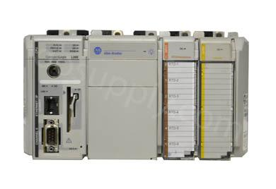
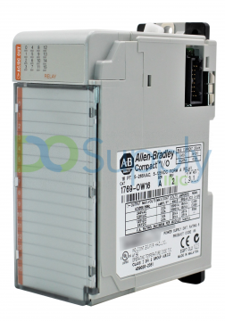
The phrase ‘inputs and outputs’ is used to refer to all of the various, multiple wiring types that a PLC can utilize to connect to outside devices, and is usually shortened to ‘I/O’. Wiring terminals are usually arranged together physically either on the chassis of a PLC and referred to as ‘onboard I/O’, or in a separate add-on card that attaches to the side of the PLC chassis, referred to as an ‘I/O module’. Larger, more powerful PLCs only utilize add-on I/O so that they’re fully modular for application customization, and smaller PLCs often utilize onboard I/O or a mix of onboard and module I/O. Therefore, an ‘output module’ is the version of these types of modules only serving output signals. Please note that we’ll use ‘output modules’ here mostly to address the most common large PLC format, but that everything described also applies to any format output you might find – onboard I/O, mixed input/output modules, remote-mounted I/O, and more.
With the stage set now, let’s jump into the differences between relay and solid-state output modules.
Relay vs Solid-State Outputs
We said above that a discrete output is a fully-on or fully-off control type, and this also means that we cannot partially energize a device or vary its power. No dimming lights, no adjusting pump speeds, no partially opening valves (this variable control is known as ‘analog control’, which will be a topic for a different article). Over the years, several different technology types have been developed to allow us to physically switch electrical signals in this way, and this is the basis for the rest of our discussion. Relay and solid-state outputs perform the same end result of turning a device fully on or off, but use different technologies to do so, and therefore have different features and benefits between their styles.
Mechanical Relay Output
The term ‘relay’ commonly refers to a mechanical switching device, in short. A relay consists of a metallic switch that functions just like a light switch – it physically moves internal metallic pieces to connect and disconnect the flow of electricity to a field device. Unlike a light switch though, a relay uses an electromagnet to perform the physical switch movement automatically when told to do so by another part of the system.
Solid-State Output
In contrast to a relay output, a solid-state output uses an electronic device with no moving parts to turn outputs on and off. The most common solid-state output design uses a transistor to perform this electronic switching, but other varieties exist as well (which we’ll describe below). Solid-state relays use semiconductors with engineered resistance features to either halt or allow the flow of electricity to a field device.
When automation engineers say ‘relay’, they are most often referring to a mechanical relay in short. If they say ‘switching output’, they are most often referring to a solid-state output.
Functional Differences – Relay vs Solid-State
The main functional difference between a mechanical relay and a solid-state relay is around power circuitry routing.
Relay Functionality
A relay output has two separate power paths. One path triggers the electromagnetic coil using a very small electrical load, and the other side connects an independent power supply to the switched output. We refer to a relay as being ‘voltage independent’ for this reason – you can mix and match AC and DC voltages between the coil side and the load side. In addition, PLC power that switches the coil side is electrically isolated from the load side, offering protection in cases of a load overcurrent or short. Typically, PLC power will be 24VDC (and so the relay coil will be 24VDC), and the load side will either be 24VDC (for energy efficiency and safety) or 120VAC (for high load capabilities).
Relay outputs are provided with two wiring terminals per output channel, one being normally closed (passing electricity when de-energized), and the second being normally open (not passing electricity when de-energized). Load power is connected to a ‘common’ terminal, which routes live supply power to the incoming side of each relay output. In some cards, you may find an individual common per each output channel, and in others, a single common shared between multiple output channels. Your field device wires up to either the normally closed (NC) or normally open (NO) terminal, depending on how you’d like your device to function. Using the NC terminal will energize the device when the output is not activated, and activating the output will open the relay and de-energize the load. Using the NO terminal will energize the load only when the output is activated, pulling in the mechanical switch and closing the circuit.
The importance of shared versus dedicated common terminals is centered on circuit protection – that is, how you employ fuses or circuit breakers to protect your components. An individual common per channel allows you to install a fuse to protect each channel independent of the others, such that if one device were to over-amp and blow a fuse, other channels and devices would not be affected. A shared common uses a single fuse to protect multiple output channels, and a single short would take down the entire bank of shared devices.
While relays can carry a load to drive field devices, they also have the inherent ability to serve as a ‘dry contact’ in which they simply complete a minimal-voltage continuity circuit to provide a discrete signal to an external device. For example, a device with its own power supply that only needs to receive an enable signal from the PLC can wire through a relay serving as a dry contact, bringing the device’s internal power to the output channel’s common, and then switching the module’s NC output to complete the circuit back to the field device.
Solid-State Functionality
A solid-state output, in contrast, has a bit more nuance to consider around voltage isolation. First, there are two most-common forms of solid-state outputs: a transistor output and a Triac output. Each has a distinct design intent and application range, explained below. For all types, a solid-state relay uses no moving parts, offers low DC and AC load capacity, and has long life spans with high reliability. Solid-state outputs are voltage dependent, and can only be used with specific voltages. Solid-states also allow for much higher operating frequencies (switching speed) since they have no moving parts, but may need additional components added in order to reduce cyclic noise and signal degradation.
Because solid-state outputs do not physically open or close a circuit, their switching capabilities are based on augmenting the flow of electricity through their semiconductor internals by means of creating and removing resistance within the load path. This technique generates heat within the solid-state switch, adds relatively-moderate resistance to the circuit, and may not be able to achieve a zero-volt condition when switched off. This last detail is known as voltage leakage – where transient voltage may still pass through an open solid-state switch, which may present functional and safety issues downstream. This also means that solid-state switches are generally not usable as ‘dry contacts’.
Solid-State – Transistor Type
The most common solid-state output design uses a Bipolar Junction Transition, or BJT, though others such as a Field-Effect Transistor (FET) are quickly gaining popularity. A transistor is used to create a ‘switching’ output by injecting voltage into one leg, which in turn closes a separate load path across two other legs of the transistor. The majority of transistors are isolated from PLC power as well, similar to relay outputs, but using highly sensitive isolation means (such as non-contact LED optical switching) that can fail under higher loads. For this reason, transistor outputs are typically used on very low loads.
Further, a transistor output has a pre-determined polarity, meaning that it can only operate on one of either the positive or the negative leg of the power circuit. This polarity assignment can be referred to as ‘Sinking’ or ‘Sourcing’, and is permanently set when a transistor is manufactured.
Sinking – the transistor switches the negative leg of the load. Also known as NPN polarity.
Sourcing – the transistor switches the positive leg of the load. Also known as PNP polarity.
Another way to conceptualize the difference is to imagine which way the electricity will flow through the output. Sinking polarity flows from the field device ‘into’ the transistor and towards the common terminal. Sourcing polarity flows from the common terminal ‘away’ from the transistor out to the field device. In either case, this flow path is uni-directional, and cannot be changed.
Solid-State – Triac Type
Triacs are a type of solid-state switch designed to handle AC loads. Unlike their transistor counterparts, Triac outputs are bi-directional, offering the flexibility of a mechanical relay but with most of the benefits of a solid-state transistor. Triacs are electrically isolated from their source power, triggered by an optical LED or infrared pilot the same as transistor switches. Triacs are fantastic at switching small AC loads, and certainly in voltages and amperages higher than a transistor, but are sensitive to over-current conditions should too large of a load be connected. In these cases, Triacs are often used with external mechanical relays to further separate high AC loads away from the PLC, but still are beneficial in using AC voltage without the need to introduce a DC sub-circuit that wouldn’t otherwise be necessary.
Triacs have another interesting design consideration that has to do with AC voltage waves. In short, AC waves oscillate in flow direction (thus ‘alternating’ current), and nuances involved with the inherent noise, hum, and spikes that come with this oscillation are amplified in tiny Triacs. Additional semiconductor components such as diacs are often added to Triac circuits, or advanced output modules with protective features built in are specified, in order to mitigate these potential issues.
Our last discussion topic will summarize these features into a helpful list, and then conclude with a few application examples.
Application Nuances
Let’s summarize the key differences between the above discrete output types, as follows:
- Relay outputs can handle either AC or DC loads, independent of the switching voltage, versus a solid-state transistor output that can only handle DC voltages, or a solid-state triac output that can only handle small AC loads (1-2 amps max usually).
- Relay outputs are mechanical and have moving parts, so they have a lower lifespan, but can handle higher loads. A solid-state output has no moving parts and can last longer, but can only handle small loads.
- Relay outputs are relatively slow to switch states, whereas solid-state outputs are much faster to switch states.
- Relay outputs provide a physically-opened circuit, such that no voltage leak can occur across the open relay. A solid-state output provides only an electronically-opened circuit, and voltage leak may occur.
- Relay outputs have virtually no resistance across their contacts, resulting in negligible OHM drop or heat. Solid-state outputs do impose measurable resistance, and this added OHM draw also translates into heat and noise across the output.
Building from the above summary of differences between relay and solid-state outputs, let’s lastly look at a quick list of example applications, and which output type might be preferrable to employ in each.
Application 1
Challenge: A water pump and tank are controlled by a 24VDC PLC. The pump is controlled to turn on when a tank is full, emptying this tank, and to turn off once the tank is pumped empty. The pump cycle is slow, taking about 15 minutes per pump-out. The water pump is controlled by switching the 110VAC coil circuit to its magnetic motor starter, with a load of approximately 1.2 amps.
Solution: In this application, we’ll use a Relay Output module for two reasons. First, we want to switch an AC load while our PLC is 24VDC. Second, the load is higher than the capacity of a Triac, and we are concerned that voltage leak through the Triac might just be high enough to not release the magnetic starter coil when turned off, locking the pump in the ‘on’ state.
Application 2
Challenge: A conveyor line uses a high-speed photo eye to count metal parts as they come out of an automatic stamping machine. A 24VDC PLC receives this photo eye input, and times an output to fire a 24VDC pneumatic valve (0.2 amp load) pointed at the parts, shooting a quick burst of clean, dry air over each part to remove any residual dust or shavings left over from the stamper. The valve may fire up to 60 times per minute.
Solution: For this job, we’ll use a Solid-State Output module, transistor style, due to having matched 24VDC voltages on all devices, a high cycle rate, and a low load. The solid-state output will offer longer life, and will be more reliable for this high-frequency application.
Application 3
Challenge: A building automation controller is installed to control lighting, HVAC, and alarm systems throughout the facility. The lighting circuits in particular need precise control, turning on and off automatically based on input from motion sensors. The lighting control circuitry is all 24VAC, and the controller is 120VAC as well.
Solution: Since we’re dealing with AC circuits, our choices are to use either a relay output, or a solid-state output of the Triac design. Comparing the two, we know that we can tolerate the minor voltage leakage, noise, and heat that will occur with the Triac. We like that the relay would allow us to drive higher loads, but after checking specs, we find that the lighting control loads are well within the Triac’s rating. We opt to go with the solid-state Triac output, swayed by its longer life and no moving parts, offering the facility engineer lower maintenance and replacement costs over the long run.
We hope that this overview of Digital Output Modules (Relay vs Solid-State) has been helpful in understanding PLC/PAC/Controller discrete output types and their respective capabilities. For more information or to discuss which PLC Control and Instrumentation solution might be best for your application, please visit our website here, or contact us at sales@dosupply.com or +1 (919) 205-4392.
DO Supply Inc. makes no representations as to the completeness, validity, correctness, suitability, or accuracy of any information on this website and will not be liable for any delays, omissions, or errors in this information or any losses, injuries, or damages arising from its display or use. All the information on this website is provided on an "as-is" basis. It is the reader's responsibility to verify their own facts.