Radio Frequency Power Conversion Calculator: What is Radio Frequency Power and How is it Calculated?
Radio Frequency Power Conversion Calculator
What is Radio Frequency Power?
Electromagnetic radiation consists of waves having magnetic and electric energy radiating together through space at the speed of light. It is described as the energy conveyed through space in a waveform, characterized in terms of frequency for wavelength λ. When all forms of electromagnetic energy are combined, they make up the electromagnetic spectrum, which is the range of frequencies produced by those sources. One form of electromagnetic energy is the Radio waves emitted by transmitting antennas. Thus, Radio Frequency (RF) is a frequency within the electromagnetic spectrum, often used for radio transmission.
Radio Frequency waves are also characterized in terms of a wavelength λ or a frequency f. Wavelength refers to the distance completed by one full cycle of the electromagnetic wave, while frequency is the number of times the electromagnetic waves pass a given point in one second. RF waves are high-frequency electromagnetic waves with a frequency ranging between 30Hz (Hertz) and 300 GHz(gigahertz).
In practical applications, RF is the oscillation rate of an alternating voltage or alternating electric current of an electromagnetic field, magnetic, mechanical, or electric system in the frequency range of about 30Hz (Hertz) to approximately 300 GHz(gigahertz). This frequency range enables energy from oscillating currents to radiate off an electrical conductor into space as radio waves. This provides the basis of radio transmission.
Radio transmission technology is the use of radio waves for signaling and communicating. These radio waves are generated by an electronic device known as a transmitter, which is connected to an RF antenna that radiates the generated waves. The emitted waves are then received by another RF antenna connected to a radio receiver, enabling radio transmissions. Thus, an RF antenna can be used to emit or receive Radio Frequency waves. As an emitter, it converts high-frequency RF signals traveling through a conductor into Electromagnetic (EM) radiations in free space.
Often, you’ll come across the term Radio Frequency (RF) power transmission, which refers to the transmission of output RF power from a transmitter to an antenna. Thus, RF power can be defined as the actual amount of radiofrequency energy produced by an RF transmitter at its output. It can be also be described as the actual input power to an antenna from a transmitter. In cases where an amplifier is used in the RF circuitry, then RF power is the actual amount of radiofrequency energy from the amplifier to an antenna.
Why is Radio Frequency Power Important?
We use RF power in almost every area of our day-to-day lives. For example, it’s through RF power that you receive your morning news, send messages through your cell phone, connect to the internet, etc. Some of the most common applications of RF power include:
A) Communications: Radiofrequency power is used in almost all communication devices such as computers, mobile phones, televisions, transmitters, and receivers. It is also applied in carrier current systems including telecommunication transmission systems and control circuits. Today, MOS (metal–oxide–silicon transistor) or MOSFET (metal-oxide–semiconductor field-effect transistor) integrated circuit is the technology behind the ongoing proliferation of RF wireless telecommunications devices like cell phones.
B) Medical Applications: Radio Frequency Power has been used in medical applications for over 75 years. The most well-known application of RF power in medicine is Magnetic Resonance Imaging. But there are many other areas in this field where RF is utilized. Some of these applications include Cosmetic Therapy, Hyperthermy, Diathermy, Tissue Ablation, Cauterization, and Cutting using higher power RF. Also, recently it has been discovered that RF power can be used to selectively kill certain viruses on non-biological surfaces such as the SARS-CoV-2 that causes Covid-19; because the structure of this virus physically resonates at around 8 GHz.
C) RF Cooking: Also referred to as solid-state cooking, RF cooking makes use of a high-power solid-state amplifier, which as part of a complete RF module, transmits solid-state radio frequencies. The resulting radio wave energy is then used to heat an object in an enclosed closed cavity like an oven. So, the energy from the radio waves in this application is more precise and controlled.
D) Radar Systems: These operate at Radio Frequencies ranging between 300 MHz(megahertz) and 15 GHz(gigahertz). They detect the presence, range, or direction of ships, aircraft, and other moving objects. They are widely used for aviation, navigation, weather forecasting, and national defense.
How is RF Power Generated?
An RF power source is a system that provides high-frequency electromagnetic fields. Normally, the term radiofrequency field or electromagnetic field is used to indicate the presence of RF or electromagnetic energy. An RF field consists of both an electric field and a magnetic field.
In an RF power source, the high-frequency electromagnetic fields resonate in an enclosed device called the RF cavity thereby generating RF power. An RF cavity is an electromagnetically resonant structure. RF cavities are commonly used inside particle accelerators to generate high-strength longitudinal electric fields which accelerate particles(beam) to a desired RF energy level.
All particle accelerators propelling charged particles to very high speeds and energies greater than 20 MeV require high-power RF sources. In such applications, radio-frequency amplifiers are commonly used to attain sufficient RF frequency and phase stability. The applied frequencies usually range from 50 MHz(megahertz) to 30 GHz or more. While the input power requirements vary from 10 kW to 2 MW or higher for continuous sources and pulsed sources, the input power range can be up to 150 MW.
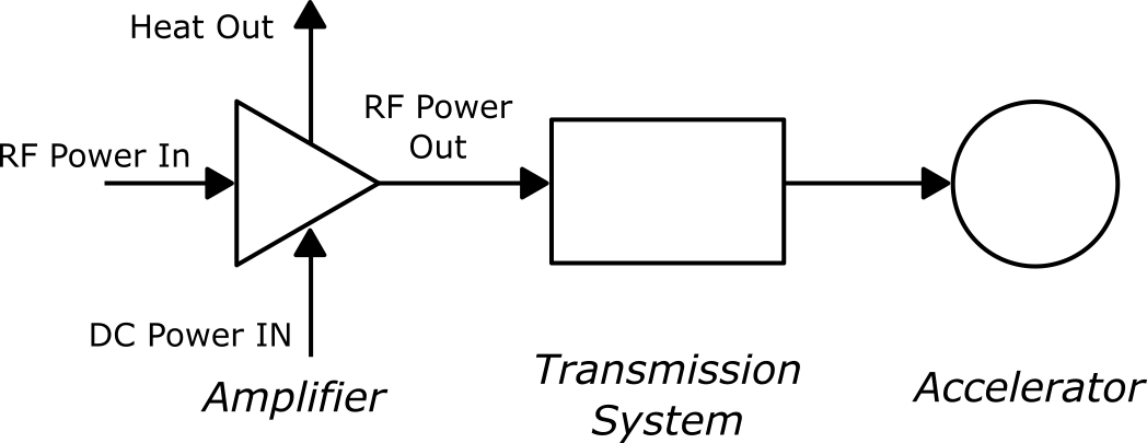
The figure above shows the main components of a generic high-power RF system. In the system, the function of the power amplifier is to convert the DC (Direct Current) input power into RF output power whose amplitude and phase are determined by the level of the input power from the RF cavity.
The transmission system components including couplers, circulators, windows, etc., transmit the RF power from the source (RF amplifier in this case) to the accelerator. The accelerating structures then use this RF power to accelerate the low-charge particles to high energies. Hence, a complete RF power system is more of an energy transformer that takes energy from low-energy, high-charge electron bunches and transfers it to high-energy, low-charge bunches of charged particles. If it’s not possible to obtain sufficient RF power from a single amplifier, then several amplifiers may be used for a higher combined RF output power. In some cases, one amplifier can be used to sufficiently supply RF power to several particle accelerators.
Role of a Radio Frequency Amplifier in RF Power Transmission
An RF power amplifier is a type of electronic amplifier which converts low-power radio-frequency signals into higher-power RF signals. Typically, RF power amplifiers are used to drive the antenna of an RF transmitter. This is because the goal of the output stage of an RF transmitter is power transfer. You don’t want to just move power from one device to another; you would want significant current to flow through the antenna so that it will have plenty of electrical energy to radiate as RF or electromagnetic energy.
Maximum RF power transfer occurs when the magnitude of the source impedance is equal to the magnitude of the load impedance. In most RF circuitry, the transmission line that connects the amplifier to the antenna (the amplifier’s output stage) will generally have an impedance of 50 Ω, so the antenna impedance should also be 50 Ω for maximum power transfer.
In these rare cases where the load impedance (antenna’s input impedance) perfectly matches the magnitude of the amplifier output impedance (source impedance), the RF power delivered to the antenna is simply the rated power of the RF amplifier. That would mean the reflected power is zero, hence, there would be no need to limit or control the amplifier’s gain to protect it from excessive reflected power. Unfortunately, you will rarely find such ideal conditions in real-world applications.
Practical RF amplifiers drive antenna with varying load impedance. The mismatch between the amplifier and antenna impedances causes a certain percentage of the forward RF power to be reflected in the amplifier. If excessive power is reflected then the amplifier is highly likely to get damaged, and precautions that may affect forward power transmission are required, such as taking account of the amplifier’s power gain.
In radio frequency circuits, the amplifier’s power gain is often more important than its voltage gain. This is because power amplifiers have low output impedance while voltage amplifiers have high output impedance. RF amplifier power gain is defined as the power difference between the amplifier’s output signal and its input signal. This power gain is most commonly expressed as transducer gain, given by:
GT = Pload / Pavail
where Pload is the power delivered to the antenna by the amplifier, and Pavail is the power available from the source (i.e., an RF cavity). When the amplifier input impedance is equal to the source impedance, then Pavail is the same as the power delivered to the amplifier from the RF cavity. The input and output impedances of the amplifier are then assumed to be the same as the characteristic impedance of that particular RF power system. Thus, the amplifier’s power gain is expressed as:
G = Pout / Pin
Where:
G = Amplifier’s power gain (dimensionless)
Pin = RF power applied to the amplifier input
Pout = RF power output from the amplifier
The amplifier’s power gain can be expressed in Decibels, which is a logarithmic ratio of the amplifier’s output power relative to its input power. This is expressed mathematically as:
PdB = 10log10 (Pout / Pin) dB,
where:
PdB = Amplifier’s power gain in decibels (dB)
Pin = RF power applied to the amplifier’s input
Pout =RF power output from the amplifier
Note, you can calculate this power gain by subtracting the input power from the output power when both power levels are expressed in dBm (decibel-milliwatts), which is decibel power in reference to 1 milliwatt(mW). The power gain of an RF amplifier is specified as a minimum value over a given frequency range. In some amplifiers, both maximum and minimum power gain are specified to ensure that the subsequent stages in the Radio Frequency power system are not under or over-driven.
How is RF Power Calculated?
How much output power can an RF amplifier provide? This age-old question is often asked by seasoned RF professionals as well as novice test engineers. Depending on the application, there is always an underlying desire to maximize any of these three parameters: voltage, current, or power. In Radio Frequency power systems, the parameter that is of great interest is the power output.
In all types of electric circuits including RF power circuitry, the power dissipated is given as the product of DC voltage across the amplifier and the RF current flowing through it. With this in mind, you may think that a simple application of Ohm’s law will be used to calculate the Radio Frequency power from an RF amplifier as:
RFout = Vo × Io
RFout = ( Vo2 ) / ( R )
RFout = Io2 × R
RFout = Amplifier’s Output Power in Watts (W)
Vo = Output Voltage in Volts (V)
Io = Output Current in Amperes (A)
However, the above equations would only be applicable in ideal conditions, such as when an RF amplifier with a typical output resistance of 50 Ω is used to drive an antenna with an input resistance of 50 Ω. But such ideal conditions rarely occur in practical applications, as antennas driven by real RF amplifiers most often have varying resistances. Also, you can be tempted to justify the use of the above power equations by considering an antenna as just a simple conductor, with very minimal(negligible) resistance.
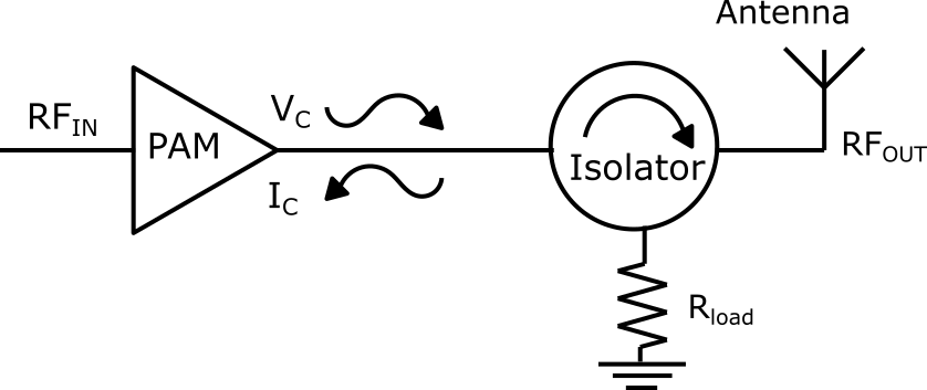
Well, it’s true that electrical conductors have negligible resistance in DC (Direct current) circuits, but you should keep in mind that antennas have significant amounts of input impedance at higher frequencies. And since an RF power circuitry with practical amplifiers and antennas involves high frequencies, then the antenna will always have a significant amount of input impedance in such circuits. This leads to impedance mismatches between the amplifier output impedance and the antenna input impedance, as shown in the diagram to the right.
Following the preceding discussion, it is therefore necessary to consider the power gain when computing the actual Radio Frequency power output from an amplifier in an RF power circuit. Hence, actual Radio Frequency power output from the amplifier can be expressed as:
RFout (actual) = RFin × G
where:
RFout (actual) = Absolute output RF power from the amplifier. Given in Watts (W) / Milliwatts (mW)
RFin = Input RF power to the amplifier. Given in Watts (W) / Milliwatts (mW)
G = Linear Power gain of the amplifier. It is dimensionless.
Note, RF signals are represented in terms of decibels and watts. In that regard, you can express Radio Frequency power in terms of watts or in decibels. The invention of the decibel unit was motivated by the fact that the human ears perceive sound intensity logarithmically, and most applications of RF power are in communications.
RF Power Levels in Decibels
dBm (decibel-milliwatt) and dBW (decibel-Watt) are common measures of absolute Radio Frequency power levels in RF engineering. In such applications, a decibel (dB) is defined as a measure of the increase or decrease in RF power levels, it’s thus a ratio and a dimensionless quantity. For example, you can express the ratio of input and output RF power in logarithmic form as:
RF Power Ratio in dB = 10log10 ( RFin / RFout ) = 10log10 ( Pin / Pout)
Note, the decibel measure can only provide the relative power levels, it does not give any information about the absolute(actual) RF power levels involved. A more useful way of comparing Radio Frequency power levels in decibels is by referencing them to a standard power level.
For low-power RF systems, like those used in mobile communications, the reference power level used is the dBm (decibel-milliwatt) scale; in which RF power in decibels is referenced to a level of 1 milliwatt (Mw). Expressed mathematically as:
P (dBm) = 10log10 [ P(mW) / 1 mW ]
whereby,
P (dBm) = RF Power in decibel-milliwatts
P(mW) = RF Power in milliwatts
For high-power RF systems, such as those used in satellite communications, the most commonly used reference power level is the dBW (decibel-Watt) scale, in which RF power in decibels is referenced to 1 Watt (W). As expressed below:
P (dBW) = 10log10 [ P(W) / 1 W ]
P(dBW) = RF Power in decibel-Watts
P(W) = RF Power in Watts
Losses and Gains in Radio Frequency power systems can easily be computed in decibels. But technically, the Watt is the most convenient unit used by engineers to determine how much RF power a piece of equipment is emitting or receiving. In the next section, we’ll look at a few examples of RF power calculations involving conversion between decibels and Watts units.
Examples of RF Power Calculations
Example 1: The linear power gain of an RF amplifier is 1200. What is the value of this power gain in decibels? If the input Radio Frequency power is 5 dBm, what is the output Radio Frequency power in decibel-milliwatts(dBm)?
Solution: The power gain of an RF amplifier in decibels (PdB) is given by the following formula:
PdB = 10log10 ( Pout / Pin ) dB,
Where ( Pout / Pin ) is the dimensionless linear power gain, so PdB can be computed as:
PdB = 10log10 (1200) dB = 30.79 dB
Previously, we had stated that you can compute the power gain by subtracting the input RF power from the output RF power, when the two power levels are expressed in dBm (decibel-milliwatts). Similarly, given the input RF power in dBm and the gain in dB, you can obtain RF output power in dBm as:
Pout (dBm) = Pin (dBm) + PdB = 5 dBm + 30.79 dB = 35.79 dBm
Example 2: A Radio Frequency signal having a power of 40 mW is applied to the input of an RF amplifier which increases the RF power of the signal by a factor of 20.
A) What is the input power of the amplifier in dBm?
Given that Pin(mW)Pin(mW) = 40 mW, then we’ll use the following formula:
Pin (dBm) = 10log10 [ Pin (mW) / 1 mW ] = 10log10 [ 40 mW / 1 mW] = 16.0206 dBm ≈ 16.0 dBm
B) What is the gain, G, of that RF amplifier in dB?
By default, the RF amplifier gain is the power gain (power increase factor), so:
G = 20 = PdB = 10log10 (20) dB = 13.0103 dB ≈ 13.0 dB
C) What is output RF power of the amplifier in Watts?
G = [ Pout (mW) / Pin (mW) ]
Pout (mW) = G × Pin (mW) = 20 × 40 mW = 800 mW
Converting 800 mW to Watts, you get 0.8 W as the output RF power.
D) What is the output power in dBm?
Since, this is a low-power RF system, we can only use the dBm (decibel-milliwatt) scale as the reference power level:
Pout (dBm) = 10log10 [ Pout (mW) / 1 mW ] = 10log10 (800) = 29.0309 dBm ≈ 29.0
Alternatively,
Pout (dBm) = PdB + Pin (dBm) = 13.0 dB + 16.0 dBm = 29.0 dBm
Radio Frequency Power Conversion Calculator
This calculator is designed to convert the values of Radio Frequency power in watts to decibels and vice versa. As you can see from the sample calculations above, converting the RF power values between the two units of measurement by hand can be very tedious, confusing, and inaccurate.
The good news is that the RF Power Conversion Calculator is a simple tool to use and it gives accurate results. All you need to do is select the preferred units for the RF input and output power, enter the value to be converted and then press the calculate button. You’ll then get the results as the value of the Radio Frequency power in the desired units.
The RF Power Conversion Calculator (shown above) allows you to convert RF output power and RF input power values from different variables including Watts (W), milliwatts (mW), dBW (decibel-Watt), and dBm (decibel-milliwatt). Its working principle is based on the following equations:
PdBm = 10log10 [ P (mW) / 1 mW ]
PdBW = 10log10 [ P (W) / 1 W]
PdBW = PdBm − 30
PmW = 10PdBm / 10
PW = 10(PdBW) / (10)
where:
PdBW = RF power in decibel-milliwatts
PdBW = RF power in decibel-watts
PmW = RF power in milliwatts
PW = RF power in watts
DO Supply Inc. makes no representations as to the completeness, validity, correctness, suitability, or accuracy of any information on this website and will not be liable for any delays, omissions, or errors in this information or any losses, injuries, or damages arising from its display or use. All the information on this website is provided on an "as-is" basis. It is the reader's responsibility to verify their own facts.