Exploring the Technology Behind Kinetix DC Drives
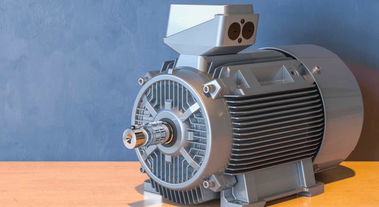
Kinetix DC drives are a type of electric servo drive developed by Rockwell Automation to specifically provide precise speed, current, and/or position control within the closed-loop circuitry of brushless or brushed DC servo motor control systems. These drives use a rectifier circuit to convert a DC or AC input voltage into the needed DC supply for the connected DC servo motor. The DC supply to the servo motor is then regulated to control the motor speed and position.
Allen-Bradley Kinetix DC drives are integral to effective motion control in various applications, including turntables, cranes, conveyors, and printing machines, for which variable speed, low speed, or constant torque are required. They offer numerous benefits such as high starting torque, linear speed-torque curve, speed control over an extensive range (both below and above the rated motor speed), accurate step-less motor speed with constant torque, quick starting, acceleration, reversing, and stopping.
The benefits mentioned above make the Kinetix DC drives an excellent choice for motor control applications that exhibit high inertia, continuous regeneration, shock loads, or rapid deceleration and acceleration rates. They can thus effectively run extruding, drawing, coating, and finishing operations. They are also ideal for upgrading existing DC machinery.
Key Drive Features
The Kinetix DC servo drives feature the following:
- Fasting-acting voltage and current limit regulation that brings about maximum deceleration/acceleration without tripping
- Programming flexibility that allows control parameters to be connected within the Kinetix DC drive
- Single-phase or three-phase regulated power supply, which depends on the size of the servo drive
- Supports both non-regenerative and regenerative operations
- Includes an armature converter and a regulated field converter
- Offers highly flexible communication and feedback options
- Incorporates voltage noise suppression filters for noise-sensitive applications
- Offers a wide variety of input and output modules for installation flexibility. Standard I/O modules include two analog outputs, three analog inputs, four digital outputs, eight digital inputs, encoder capabilities, and a DC tachometer
- High-speed analog inputs that improve the response of the DC servo drives to speed or torque commands
- Various Kinetix DC drives feature a NEMA/UL, IP20 Open-Type enclosure for conventional mounting of the drives either outside or within a control cabinet
- Integral liquid-crystal display (LCD) keypad and software tools for drive configuration and programming
- Features an advanced regulator with encoder capability, DC tachometer, and integrated DPI (Drive Peripheral Interface) functionality
- Available with optimized global voltage settings, which are developed to global standards
- Supports in-field firmware updates through a DPI communication interface
- Integral process PI (Proportional Integral) control, which eliminates the need for an independent controller for process control loops
- Flying Start feature that provides a smooth and on-the-spot connection into a rotating load, irrespective of the commanded motor direction, and without requiring any speed feedback
- Closed-loop or Open-loop speed regulation functions:
- DC tachometer feedback delivers a maximum of 0.1% speed regulation
- Armature feedback delivers a 2000:1 RPM speed range
- Encoder feedback delivers a maximum of 0.1% speed regulation for applications with the tightest requirements
- TorqueProve feature, which helps ensure control of the connected load when motor control is shifted between the Kinetix DC drive and a mechanical brake
- Closed-loop or Open-loop torque regulation functions:
- Encoder feedback (closed-loop torque regulation) delivers ±1% torque regulation and the capability to hold the full load at zero motor speed
- Open-loop motor torque regulation delivers ±5% regulation
The Technology behind Kinetix DC Drives
To fully comprehend the technology behind the Kinetix DC drives, we’ll need to identify the components that make up these drive systems and discuss their working principle.
Drive Components
Allen-Bradley Kinetix DC servo drives feature a compact design incorporating a common control structure and a fully self-contained power module for the entire range of their regulated field supply. The standard Kinetix DC drive hardware consists of the following:
Armature Converter
In Kinetix DC drives, the armature converter transforms the supplied AC voltage into DC voltage. By adjusting this converter’s firing angle (α), the DC voltage to the connected DC servo motor can be varied to obtain an operating speed below the motor’s base speed. This DC motor control method is called the constant-torque drive technique, whereby the motor armature voltage is adjusted from zero voltage to the motor’s rated voltage. In contrast, the magnetic flux and armature current are maintained at their rated values. Note that torque output is directly proportional to flux and armature current in DC drives.
Regulated Field Converter
A regulated field converter is needed in Kinetix DC drives for economy or field-weakening applications. Flux weakening or field weakening is a technique of reducing the current being applied to the shunt (field) windings of a shunt wound DC servo motor. It seeks to extend the speed range of the DC shunt motor at the maximum available supply voltage, allowing it to operate at speeds above its rated RPM but at the expense of reduced output torque. In shunt wound DC servo motors, the field excitation current is independent of the armature circuit current, so it’s possible to control the field current independently.
Kinetix DC drives that use field weakening control to extend the speed ranges of connected DC servo motors feature an automated provision to control both the field current and armature voltage when running. For this reason, an extra adjustable voltage field regulator is required for the Kinetix DC servo drives with field voltage control.
Note: The regulated field converter enables Kinetix DC drives to provide field-flux motor control for high-speed operations where operating speeds above the base speed are required. The armature current and voltage are maintained at their rated values during field-flux control. At the same time, the shunt field flux is reduced to significantly increase the operating speed of the motor being controlled above its base speed. As a result, this method of DC motor control is referred to as the constant-power drive technique. And since field flux is directly proportional to torque in DC shunt motors, the torque output of the connected DC servo motor will decrease as the field flux is reduced.
Advanced Regulator
Allen-Bradley DC drives incorporate an advanced regulator with fully integrated DPI (Drive Peripheral Interface) functionality. This allows the DC drives and associated DC field controllers to be fully compatible with various Rockwell Automation HIMs (Human Interface Modules), AC drive communication cards–Architecture Class, and software tools.
DC Field Controller
Allen-Bradley DC field controllers are designed for Kinetix DC digital drives, DC Standalone Regulators (SARs), or standalone field control applications of DC servo motors. They provide three-phase, reversing (four quadrants) field control for DC servo motors or generators. An optional fiber-optic communication interface module, or an analog and digital I/O module, is used to provide a means of transmission for reference, status, and feedback signals between the DC field controller and a Kinetix DC drive, or between a standalone regulator and the DC field controller.
In standalone motor control applications, the DC field controller supplies power to a DC servo motor field with a predetermined voltage reference using a fixed I/O. The controller may also be used to provide regulated power to highly inductive loads or non-motor DC loads. Non-motor DC loads include synchronous motor excitation circuits, electromagnets, galvanic applications, etc.
In addition, the DC field controller is an economical solution for migrating field controls for DC servo motors while repurposing/still using existing motor-operated equipment. It is also suitable for DC retrofit control applications requiring motor reversing. It allows users to modernize their DC motor controls using an existing DC servo motor and external power bridge.
DC Standalone Regulator
The DC Standalone Regulator (SAR) is an Allen-Bradley DC drive regulator that provides a regulated field supply, armature SCR (Silicon-Controlled Rectifier) gate signals, and armature regulation. Combined with a Gate Amplifier, the SAR provides an integrated control solution for external DC power modules connected to a Kinetix DC drive system.
The field supply of a typical Allen-Bradley DC Standalone Regulator comprises a single-phase, non-reversing (two quadrant) full-wave bridge rectifier, available in 70 amps or 40 amps. The SAR supports a field input between 100 and 460V AC and an AC line input voltage between 230 and 690V AC.
Working Principle of Kinetix DC Drives
Kinetix DC servo drives are power modules or amplifiers that interface between a DC field controller and a DC servo motor. A common way of classifying DC servo motors is by how their field windings are connected. Shunt-wound DC servo motors are the most widely used type for variable-speed control. In most cases, a constant-level voltage from the DC field controller excites the shunt field winding.
A Silicon-Controlled Rectifier (SCR), also referred to as a thyristor, is part of the power conversion unit of a standard Kinetix DC drive. It converts the incoming constant-voltage alternating current (AC) to a variable-voltage, regulated direct current (DC) output, which is applied to the armature of the connected shunt-wound DC servo motor. Motor speed control is then realized by regulating the amount of DC voltage applied to the armature of the DC shunt servo motor.
It is worth noting that, in shunt wound DC servo motors, the motor speed is directly proportional to the armature voltage but inversely proportional to the shunt field current. Also, the armature current is directly proportional to the torque output of the DC servo motor. Therefore, the speed of a DC servo motor can be varied by reducing or increasing the applied armature voltage. Nevertheless, this is only possible up to the rated supply voltage. For motor control applications requiring a higher operating speed than the rated RPM speed (base speed), the shunt field current of the DC servo motor has to be reduced.
Let’s discuss the functions of every DC drive circuit component:
Supply Unit: This module supplies the DC drive with its rated voltage.Most thyristor-based Kinetix DC drives operate on a single-phase power supply, requiring four thyristors to achieve full wave rectification. A three-phase power supply is used to control larger DC servo motors as much smoother waveforms are needed. In such applications, six thyristors are required to achieve full wave rectification.
Rectifier Bridge: The power element of a controlled Kinetix DC drive is a full-wave thyristor bridge rectifier driven by either a single-phase or three-phase supply voltage. As previously mentioned, the electrical phase of the supply voltage determines the number of thyristors to be included in the bridge rectifier.
In a nutshell, the primary function of a Kinetix DC drive is to convert the applied fixed-voltage AC input into a modulated, variable-voltage DC output. The thyristors or switching power semiconductors in the rectifier bridge provide a suitable technique. They rectify the supplied AC input voltage into a DC output voltage to be applied to the armature of the connected DC servo motor. The amount of DC voltage being provided to the connected DC servo motor is then controlled by adjusting the firing angle of the thyristors to obtain the desired motor speed. The firing angle is the point in time where the thyristors are triggered into conduction.
Field Supply Module: The function of this component is to deliver a constant voltage to the shunt windings of the connected DC motor to generate a constant magnetic flux or field in the motor. In some instances, this unit includes a diode rectifier or thyristor bridge to reduce the voltage being applied to the field winding to regulate the operating speed of the connected DC motor above its rated RPM (base speed).
The voltage supplied to the field winding is considerably lower than the armature voltage; hence, in most cases, a single-phase field supply unit is provided in Kinetix DC drive circuits. In other cases, a two-phase field supply can be drawn from a three-phase power unit supplying the motor armature. This requires a field exciter in the armature’s power supply unit.
Note: The field supply module is not incorporated in the DC drive circuit for control applications involving permanent magnet DC servo motors.
Speed Regulation Module: This unit compares the desired motor speed (as programmed by an operator) with speed feedback signals and sends appropriate command signals to the drive’s firing circuit. In analog DC drives, the speed regulator unit comprises both current and voltage regulators. The voltage regulator receives a speed error signal as input, and in response, it produces a voltage output that’s then applied to the current regulator.
On receiving that voltage, the current regulator generates the right amount of current that’s required by the firing circuit. If more speed is desired, the supplemental current is requested from the voltage regulator, and as a result, the thyristors of the Kinetix DC drive’s main bridge rectifier conduct for more periods. Normally, this type of speed regulation (both current and voltage) is realized with Proportional-Integral-Derivative (PID) controllers.
A field current regulator is also included in applications where the required operating speed of the DC motor being controlled is greater than its base speed. In modern-day microprocessor-based digital DC drives, motor speed control is achieved with the help of a lookup table that is used to determine the amount of current required by the drive’s firing circuit featuring additional digital circuitry.
Firing Circuit: This gate drive circuit provides gate pulses (logic signals) to the thyristors of the DC drive’s main bridge rectifier, enabling them to turn ON for given periods to produce a variable armature voltage. It also provides electrical isolation.
DO Supply Inc. makes no representations as to the completeness, validity, correctness, suitability, or accuracy of any information on this website and will not be liable for any delays, omissions, or errors in this information or any losses, injuries, or damages arising from its display or use. All the information on this website is provided on an "as-is" basis. It is the reader's responsibility to verify their own facts.