The Relationship Between PowerFlex Drives and Motor Bearing Damage
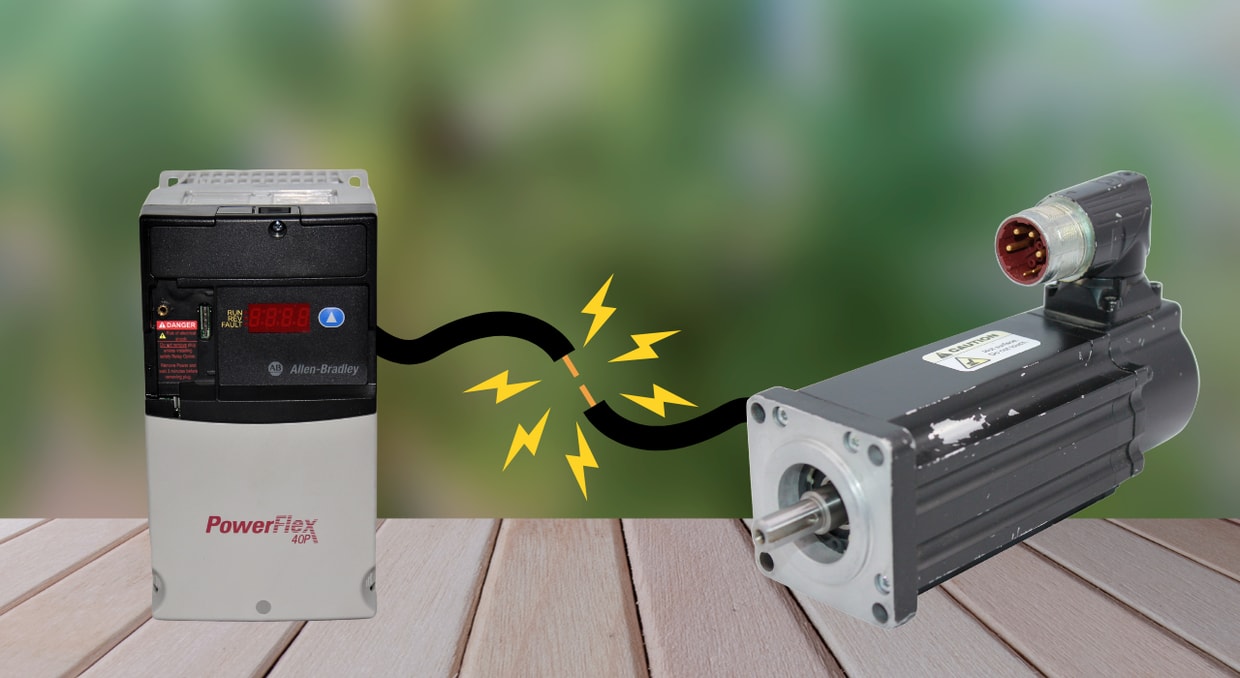
Variable Frequency Drives (VFDs) are widely used in modern industries to optimize process control, minimize power consumption, and extend equipment lifespan. The Allen-Bradley PowerFlex series stands out for providing high-performance motor control with precise torque control and simplified automation integration. However, VFD operations can induce damaging high-frequency stray currents and common-mode voltages on motor shafts. These high-frequency currents often discharge through the motor bearings, resulting in accelerated bearing wear and premature equipment failure.
The destructive impact of VFD-induced high-frequency currents on motor bearings is a widely recognized engineering issue. Connecting standard AC motors to variable frequency drives (VFDs) like the PowerFlex drives exposes them to stray currents and high-frequency voltage spikes. When under pure sinusoidal utility power, destructive stray currents do not exist. Catastrophic mechanical failure and structural degradation result when these unmanaged currents discharge directly through the motor bearings. They cause electrical discharge machining (EDM) pits, fluting on the bearing races, and ultimately damage the motor bearings.
This article analyzes the root causes, electrical mechanisms, and mitigation strategies related to this phenomenon. It is a critical resource for equipment operators and maintenance personnel seeking to prevent unexpected downtime and extend the lifespan of AC motors driven by PowerFlex drives.
The Root Cause: PWM Switching Architecture and Common Mode Voltage
To precisely control the speed and torque of AC motors, PowerFlex drives synthesize variable frequency and artificial AC voltages using high-speed IGBTs (Insulated-Gate Bipolar Transistors) and PWM (Pulse Width Modulation) switching. The rapid switching of IGBTs creates high-frequency Common Mode Voltage (CMV) pulses on the motor’s stator windings. The generated CMV makes use of the motor’s internal parasitic capacitance to couple onto the rotor shaft. This creates damaging shaft currents that discharge through the motor bearings.
The Role of IGBTs and High Switching Frequencies
Standard utility AC power supplies a smooth, three-phase sinusoidal voltage, in which the sum of the three phases is precisely zero at any given millisecond. In contrast, PowerFlex drives generate their own alternating current by employing a three-step pulse width modulation (PWM) conversion process. The process entails:
- Rectification: It utilizes a diode bridge to convert incoming AC utility power into pulsating direct current (DC) output
- DC Bus Filtering: This step makes use of high-capacity capacitors smoothen the pulsating DC output into a stable, continuous DC voltage
- Inverter Section: Highly effective IGBTs are used to rapidly switch the filtered DC voltage on and off every second using PWM. During the switching, the smoothened DC bus is chopped into variable-frequency, variable-voltage pulses.
Using pulse width modulation (PWM), an artificial three-phase sine wave is synthesized to control the AC motors connected to the PowerFlex drives. The carrier frequency of modern PowerFlex drives is very efficient for precise torque and speed control, despite it ranging between 2 kHz and 15 kHz. The variable-voltage pulses generated by the IGBTs in the inverter section shoot up sharply as the transistors change states nearly instantaneously. The speed of these rapid state transitions is expressed mathematically as the rate of voltage change over time (dV/dt).
Generation of Common Mode Voltage (CMV)
The three output phases of the inverter section of PowerFlex drives do not sum to zero at every instant. This is because PWM dynamically alternates the IGBTs between the positive and negative filtered DC bus rails, instead of outputting perfectly balanced, continuous three-phase sinusoidal waves. The instantaneous voltage difference between the inverter’s ground reference and the three-phase AC input is referred to as “Common Mode Voltage” (CMV).
In essence, CMV is a high-frequency, high-speed (dV/dt) waveform inherently produced
by the PWM fast-switching of IGBTs in the PowerFlex VFDs’ inverter section. It always seeks low-impedance return pathways—primarily through the motor’s internal parasitic capacitance—back to the DC bus ground. Because of parasitic couplings and electromagnetic asymmetries intrinsic to electric motors, CMV frequently induces highly capacitive, destructive currents that couple onto the rotor assembly via parasitic capacitance, often discharging through the motor bearings.
Electrical Mechanisms of Motor Bearing Degradation
In a PowerFlex drive system, when the generated high-frequency Common-Mode Voltage couples onto the rotor shaft through parasitic capacitances, such as and
, it induces a trapped shaft voltage. The bearing’s lubricant film acts as a dielectric capacitor, storing the stray voltages building up on the rotor shaft until it reaches its breakdown limit.
When the trapped shaft voltage exceeds the insulation limit of the bearing’s lubricant, the capacitively coupled current arcs across the bearing. This triggers microscopic Electrical Discharge Machining (EDM), a harmful phenomenon in which localized, intense heat from the electric arcs vaporizes tiny portions of the bearing raceway and roller/ball surfaces. Over time, repeated arcing causes frosting and microscopic pitting, ultimately leading to fluting (washboard-like ridges) in the motor bearing races in a PowerFlex drive system.
Parasitic Capacitance and Shaft Voltage Induction
In most industrial applications, from simple fan and pump control to complex, heavy-duty conveyors, Allen-Bradley PowerFlex drives are used to control the speed and torque of AC induction motors precisely. The copper stator windings of standard induction motors are separated from the steel stator core by electrical insulation to prevent short circuits. There also exists a physical air gap between the stator core and the motor’s rotor, which enables magnetic coupling and free rotation. This arrangement inherently creates parasitic capacitance within the induction motor, since a capacitive effect is formed when a dielectric insulator separates any two conductors.
As previously discussed, the operation of a PowerFlex drive generates a high-frequency Common-Mode Voltage (CMV) that capacitively couples into the rotor. This capacitive coupling acting across the motor’s internal parasitic capacitances induces damaging shaft voltages. The fundamental parasitic capacitances that form this capacitive network with an AC induction motor include:
- Winding-to-Stator Capacitance (
): The capacitance that’s formed between the current-carrying copper stator windings and the grounded steel stator core, separated by the turn and slot wedge electrical insulation. Its value dictates how the generated CMV induces destructive shaft voltages as well as bearing currents.
- Stator-to-Rotor Capacitance (
): The parasitic capacitance formed between the rotor and steel stator core. It serves as a capacitive coupling pathway for high-frequency CMV, influencing the accumulation of damaging shaft voltages that cause Electrical Discharge Machining (EDM) and motor bearing degradation in PowerFlex drive systems.
- Winding-to-Rotor Capacitance (
): This parasitic capacitance links the rotating rotor to the stator windings using the air gap and stator slot/wire insulation as the dielectric medium. It functions as a voltage divider, allowing CMV to build up on the rotor shaft and induce damaging EDM currents in the motor bearings.
These parasitic capacitances are charged when PowerFlex drives continuously inject high-frequency CMV into the stator windings. The rotor shaft acts as the immediate capacitive plate and is electrically isolated from the grounded motor frame by the bearing’s non-conductive lubricant. Shaft voltage is induced when the Common-Mode Voltage is coupled into the rotating shaft electrostatically.
Electrical Discharge Machining (EDM) Currents
An extremely thin layer of grease ranging from 0.1 to 2 microns completely separates the bearing surfaces, preventing metal-to-metal contact while the connected AC induction motor is operating at its rated speed. This microscopic grease film acts as a dielectric barrier, preventing direct physical contact between the bearing races and rolling elements (rollers or balls) during motor operation.
During operation, Allen-Bradley PowerFlex drives induce high-frequency voltages on the shafts of connected AC motors. As this shaft voltage accumulates and discharges rapidly, it exceeds the dielectric breakdown limit of the bearing’s lubricant, which typically ranges from 15 to 30 Volts. This causes the microscopic grease film to experience electrical breakdown, resulting in destructive electric arcs that physically pit the bearing raceways and rollers/balls.
Within a split second, the accumulated electrical energy discharges into the bearing through a microscopic, highly concentrated electric arc. A process termed “Electrical Discharge Machining.” During this process, the temperatures can skyrocket to 1000 C, vaporizing a microscopic volume of steel from the bearing races and rolling elements (balls or rollers).
High-Frequency Circulating Currents
The primary mechanism causing bearing damage in large AC induction motors (typically over 100 HP / 75 kW) operated by Allen-Bradley PowerFlex is high-frequency circulating currents. The sharp rise and fall (high dV/dt) of the PowerFlex output pulses generate unbalanced, high-frequency magnetic flux that links the rotor and stator frame. Fluctuations in this magnetic flux induce a continuous axial voltage along the rotor shaft—following Faraday’s Law of Induction.
This continuous voltage drives current in a loop down the shaft, through the non-drive end bearing, across the motor frame, and back through the drive-end bearing.
The induced axial voltage drives current in a loop down the rotor shaft, through one bearing, across the frame of the connected motor, and back via the opposite bearing. These high-frequency circulating currents can damage the motor bearings faster because, unlike the capacitive discharge currents due to CMV that only arc intermittently, the circulating currents flow continuously as a low-impedance loop. They break down the bearing’s lubrication film and cause rapid continuous electric arcing, which leads to micro-cratering, welding, and eventually bearing fluting. Insulating the no-drive-end motor bearing and installing a shaft grounding ring on the drive-end bearing can break the current loop, thereby mitigating this bearing damage.
Physical Manifestations of Bearing Damage
In unprotected PowerFlex drive applications, high-frequency Common-Mode Voltage and circulating currents routinely break down the motor bearings’ lubricating film. This generates uncontrolled electrical arcing—often referred to as Electrical Discharge Machining (EDM). This continuous electric arcing causes destructive and irreversible metallurgical changes to the bearing raceways and rolling elements, bringing about a cumulative degradation process that ultimately causes catastrophic motor bearing failure.
After just a few months of operation, AC induction motors running on unprotected PowerFlex drives often exhibit the following damaging microscopic structural transformations.
- EDM Micro-Pitting: When the accumulated shaft voltage breaks down the bearing’s lubricant film, micro-arcs (Electrical Discharge Machining) jump between the bearing races and rolling elements. The resulting intense localized heat melts microscopic volumes of metal from the bearing surface. The rapid quenching and removal of this molten material leaves a microscopic, volcano-like crater (pit) on the bearing surface. Millions of these microscopic craters or micro-pits accumulate along the loading paths of both the inner and outer bearing races, marking the onset of bearing degradation
- Frosting: Consecutive microscopic electrical arcing causes the original mirror-polished surfaces of bearing races to degrade into a visible matte-grey texture known as frosting. This damage compromises the surface hardness and integrity of the motor bearing, ultimately reducing its load-carrying capacity.
- Lubricant Degradation: This type of degradation extends far beyond the steel components of the motor bearing. The extreme heat produced by the EDM micro-arcs causes localized pyrolytic cracking of the microscopic grease film used to prevent metal-to-metal contact between the bearing races and rolling elements. The breakdown of the polymer chains of the grease film brings about carbonization and total loss of viscosity. The grease often becomes very hardened and black, leading to bearing seizure and overheating.
- Fluting: This is an advanced destructive phase of the Electrical Discharge Machining (EDM) phenomenon. It is caused by the destructive shaft voltages—induced by the PWM fast-switching of IGBTs in the PowerFlex VFDs’ inverter section—discharging continuously through the motor bearings. The repeated electrical arcing creates microscopic craters, and as the rolling elements (balls/rollers) pass over these craters, continuous vibration and mechanical stress imprint characteristic washboard-like ridges (dark parallel grooves) into the bearing race. These grooves cause the rolling elements to bounce from one ridge to another. This leads to mechanical damage, audible noise, and vibration that indicates bearing damage.
Engineering and Installation Best Practices
To effectively prevent premature motor bearing damage in PowerFlex drive applications, isolated modifications to either the drive or connected AC induction motor are rarely sufficient. Because this damage arises from high-frequency shaft voltages and electrical discharge machining, resolving it requires a holistic, multi-point approach that combines the correct motor modifications with proper PowerFlex drive system installation. Here are some of the best engineering and installation practices required to prevent premature motor bearing failure:
Shaft Grounding Rings
Installing a Shaft Grounding Ring (SGR) is a highly effective technique for protecting the bearings of low-voltage motors operated by PowerFlex drives—typically those under 75 kW/100 HP. The SGR rings, like the AEGIS motor bearing protection ring, encircle the rotor shaft using rows of conductive microfibers. Because these microfibers have a significantly lower electrical resistance than the motor bearings, they provide a low-resistance path that safely discharges the harmful shaft voltages to the motor frame, bypassing the motor bearings. This prevents electrical arcing through the bearing races and rolling elements.
Insulated Bearings
As previously discussed, the primary mechanism causing bearing damage in large AC induction motors (typically over 100 HP / 75 kW) operated by Allen-Bradley PowerFlex is high-frequency circulating currents. These currents can overwhelm standard shaft grounding rings as they loop continuously through the rotor shaft and motor frame. To completely protect the motor bearings, industry best practice is to install electrically insulated motor bearings—or a combination of a shaft grounding ring on one end to discharge capacitive shaft voltage and an insulated or hybrid bearing on the other end to physically block the high-frequency circulating current.
- Ceramic-Coated Bearings: These are insulated standard steel bearings where either the inner or outer bearing race is coated with a highly durable, dielectric ceramic material, usually aluminum oxide. This layer helps break the current path of high-frequency circulating currents.
- Hybrid Bearings: These motor bearings have standard steel races and non-conductive rolling elements made of ceramic, usually silicon nitride. They are a great choice for highly sensitive, high-frequency PowerFlex drive applications, as they provide complete electrical isolation because the rolling elements are themselves insulators.
VFD-Rated Shielded Symmetrical Cables
These cables ensure proper electrical installation of PowerFlex drives with 360-degree shield bonding, which significantly reduces high-frequency, common-mode voltages that cause motor bearing fluting. They feature a symmetrically balanced 3-ground(3G), 3-conductor (3C) geometry. To handle the drive-induced high-frequency harmonics, these cables are made with:
- Three separate phase conductors symmetrically arranged.
- Three bare ground cables running alternately between each phase conductor.
- A combined foil and braided copper shield enclosing the cable structure.
Output Filters or Chokes
You can install high-frequency dV/dt filters (common-mode chokes) or load reactors on the PowerFlex drive output to damp rapid voltage rise rates (dV/dt) and dampen induced stray high-frequency currents before they reach the connected AC motor. In addition, installing a sine wave filter in the output terminals between the PowerFlex drive and the connected motor helps to completely remove the PWM carrier frequency, delivering true sinusoidal voltage to the motor.
For those looking to protect their PowerFlex VFDs, repair their motors with VFD cables, or looking for replacement parts, visit our site! We carry the PowerFlex line, Allen-Bradley motors, and filters to help keep your setup running as smoothly as possible. Have a malfunctioning drive? Contact our team to get a repair quote. Otherwise, feel free to check out our blog post here about the hidden costs of running oversized drives.
DO Supply Inc. makes no representations as to the completeness, validity, correctness, suitability, or accuracy of any information on this website and will not be liable for any delays, omissions, or errors in this information or any losses, injuries, or damages arising from its display or use. All the information on this website is provided on an "as-is" basis. It is the reader's responsibility to verify their own facts.