Why Some Motors Run Hot When Paired with VFDs
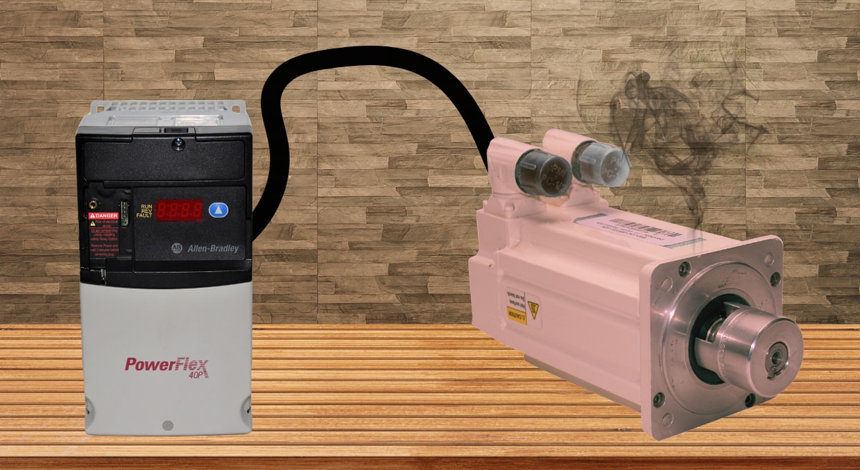
When it comes to installing motor drives, there are three different ways to do it: Exactly by the book to ensure maximum efficiency, the “yeah, that looks about right” way, and the wrong way. The by-the-book way will go exactly as you would expect. It’s the “about right” way that may lead to unforeseen struggles, such as a hot motor, when the smaller details are overlooked. Believe us, there is no shame in these installs, and if you’re wondering why your motors are getting hot after a VFD install, stick around to find out why.
Why it is Important to Keep your Motor and its Insulation Cool
Heat is the leading cause of industrial motor failure. The 10-Degree Rule is a good baseline to calculate motor insulation degradation based on how hot the motor is running relative to its rated temperature:
- -20C leads to 4x longer life
- -10C leads to 2x longer life
- +10C leads to 2x shorter life
- +20C leads to 4x shorter life
Your motor will have an insulation class rating that indicates the maximum temperature to avoid exceeding. You will see the following NEMA classifications:
- Class A: 105C, low duty and specialty equipment
- Class B: 130C, general-purpose and standard-duty motors
- Class F: 155C, industrial grade motors
- Class H: 180 °C, heavy-duty motors designed for harsh environments
Each class of motor uses different insulation materials to prevent the internal copper windings from shorting out to the case. For example, NEMA class A motors might use paper, celluloid film, or enamel, while class H motors might contain mica, glass fiber, silicone polymers, or silicone resins. If the insulation fails and the motor is grounded, it will need to be stripped and rebuilt to be used again.
So, along with other preventative measures we discuss in this article, buying properly rated motors will also save some headaches when dealing with heat, especially in warmer environments.
Why it’s Uncool to Neglect Cooling
Sometimes it’s the little things that are misjudged or miscalculated during a motor installation, and cooling isn’t an exception. Adding a VFD into the equation may exacerbate this issue as well.
Poor Airflow Around the Motor
Air-cooled systems require sufficient airflow to transfer heat from the motor’s case to the ambient air. If the ambient air is already saturated in a temperature close to the motor’s case, the rate of heat transfer will be significantly reduced. This is why ventilation and airflow are important during these installs. Providing cooler ambient air gives the motor’s heat somewhere to go, while airflow increases the rate of heat transfer by constantly circulating cooler air around the motor’s casing.
Dust can also prevent proper airflow, so make sure the installation space or cabinet is also cleaned out and dusted to ensure optimal airflow.
Low-Speed Operation with a VFD
All motors come with speed limitations. This is due to the inherent design of motors using shaft-mounted fans for cooling. If the motor slows down, so does that cooling fan. While the motor may still produce meaningful torque, there won’t be sufficient air running across the frame.
Being mindful of your motor’s minimum and maximum speeds is important during an install not only for cooling but also to prevent overload faults when going too fast and the motor being unable to sense itself when going too slow. If a lower speed cannot be helped, adding additional cooling to the motor will be very beneficial to preserving the motor’s life.
Incorrect Drive Settings
If you find that your motor is getting hot even with proper cooling and operation speeds, it might be best to check the drive settings next. A VFD needs accurate motor data to properly control voltage, frequency, current, and torque, and to provide protection. If those values are wrong, the motor may run hotter than expected, even if the hardware itself is fine.
Motor Nameplate
The first place to check is the motor nameplate information. Settings like motor voltage, full-load amps, base frequency, base speed, horsepower, and overload protection should match the actual motor being used. If the drive thinks it is controlling a different motor, it may apply the wrong voltage, allow too much current, or fail to protect the motor correctly.
Incorrect Control Settings
Having your VFD dialed in incorrectly can cause inefficiencies. Torque boost is one worth watching. A little boost can help a motor start or run at low speed, especially under heavier loads. Too much boost, however, can push extra current into the motor when it does not need it. That extra current turns into heat. Wrong carrier frequency is another, but we will go over that later.
Incorrect VFD Sizing
Just as it is important to match the motor’s nameplate to the VFD, it’s also important to install an appropriately sized VFD. If a VFD is undersized, it will continuously draw more current than it is rated for, causing excessive heat and, if severe enough, even burnout.
PWM and how it Affects Motors
To help understand why some motors run hot with a VFD, it helps to understand how the drive actually powers the motor. A VFD will not just lower the voltage to the motor in a smooth sine wave and call it a day. Instead, it uses pulse-width modulation (PWM) to rapidly switch the output voltage on and off.
PWM is a widely used technology, seen everywhere from digital-to-analog conversions to how you adjust the brightness of your phone’s display. In motor control, the drive creates a simulated sine wave by sending the motor a series of rapid voltage pulses. On or off, high or low, over and over. The VFD can control the motor’s speed and torque depending on how long the pulses are on. This technology works very well, which is why VFDs are used everywhere from conveyors and pumps to fans, compressors, and production equipment. The catch is that the motor is no longer being fed the same clean utility sine wave it was originally designed around. Instead, it is seeing high-speed switching pulses with sharp voltage edges.
Those sharp voltage edges can stress the motor insulation, especially in older motors or those not designed for inverter-duty operation. PWM can also cause additional electrical losses within the motor, which may appear as extra heat.
PWM Induced Current Ripple
Another piece of the VFD heating puzzle is current ripple. The motor’s inductance helps smooth the PWM pulses into usable current, but it does not completely remove the ripple. Some amount of ripple current remains on top of the current being used to produce torque.
This relationship could be best described with the formula: Ipp(max) = Vcc / (4 * fPWM(Lmotor + Ladd))
- Ipp(max) = Maximum peak-to-peak current ripple
- Vcc = Controller supply voltage
- fPWM = PWM switching/carrier frequency
- Lmotor = Motor inductance
- Ladd = Added inductance, such as a line/load reactor or output choke.
This formula shows the basic relationship between current ripple, supply voltage, and inductance. The higher the DC bus voltage, the higher the current ripple peaks will be, while a higher PWM frequency and more inductance can reduce them. However, this doesn’t always mean that you should crank the frequency as high as possible. Higher carrier frequencies can reduce motor noise and current ripple, but they can also increase drive heating and create other high-frequency concerns.
A more practical way to reduce ripple-related problems is to follow the VFD manufacturer’s recommendations. Depending on the installation, this may include adjusting the carrier frequency, using an inverter-duty motor, adding an output reactor, adding a dV/dt filter, or using a sine-wave filter.
Why Cable Length Matters
As we mentioned before, PWM does not produce a clean sine wave for the motor to operate on. When this is paired with longer cable runs from the VFD to the motor, there is an opportunity for voltage drop, reflected waves, leakage current, and electrical noise. We do have an article here going over cable length, specifically if you’d like a deeper dive into this issue.
The basic idea is that longer conductors (cables) create more resistance, leading to voltage loss as heat within the cable itself. If the motor receives less voltage than it expects, it may draw more current to do the same work, thereby adding even more heat to the system.
Because of this, cable length should never be treated as an afterthought of motor or VFD installations. If a cable length longer than the manufacturer recommends is needed, there are ways to work around it, such as proper shielding and grounding, an output reactor, a dV/dt filter, a proper VFD cable, or a sine-wave filter.
Final Thoughts
Having a motor heat up enough to reliably cook chicken on it after a VFD install is understandably frustrating. Thankfully, there are workarounds, fixes, and troubleshooting methods to help keep your system as efficient as possible. So whether you’re fixing an improper install or just planning your next one properly, we hope this article helps!
For those who have burnt their motors or have damaged their VFDs, we at DO Supply offer our repair services to get your system back on track. We also have motors, VFDs, PLCs, and supporting equipment on standby to help support your automation solution. Give us a call today and let us help keep your system cool!
DO Supply Inc. makes no representations as to the completeness, validity, correctness, suitability, or accuracy of any information on this website and will not be liable for any delays, omissions, or errors in this information or any losses, injuries, or damages arising from its display or use. All the information on this website is provided on an "as-is" basis. It is the reader's responsibility to verify their own facts.