Regenerative vs Non-Regenerative DC Drives
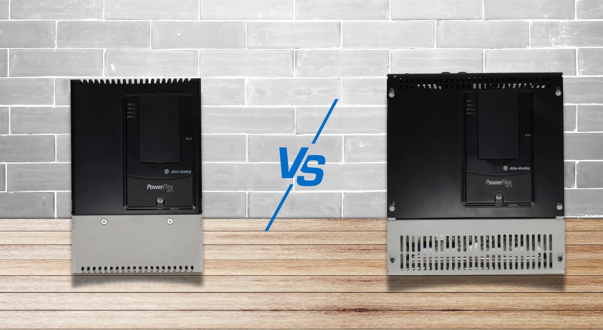
DC drives continue to play a crucial role in heavy industrial applications that need outstanding starting torque, accurate speed control, and quick dynamic response, even though AC variable frequency drives have significantly increased their market share. DC drive technology is still used in a number of industries, including material handling, elevator systems, crane operations, paper making, and metal processing. Performance capabilities, energy efficiency, hardware complexity, and long-term operating costs are all determined by the basic differences between regenerative and non-regenerative DC drives. This page offers a thorough technical comparison of these drives, backed by up-to-date performance measures and industry statistics.
Quadrant Operation: The Foundational Difference
The operational quadrant capability represents the most fundamental distinction between these drive types.
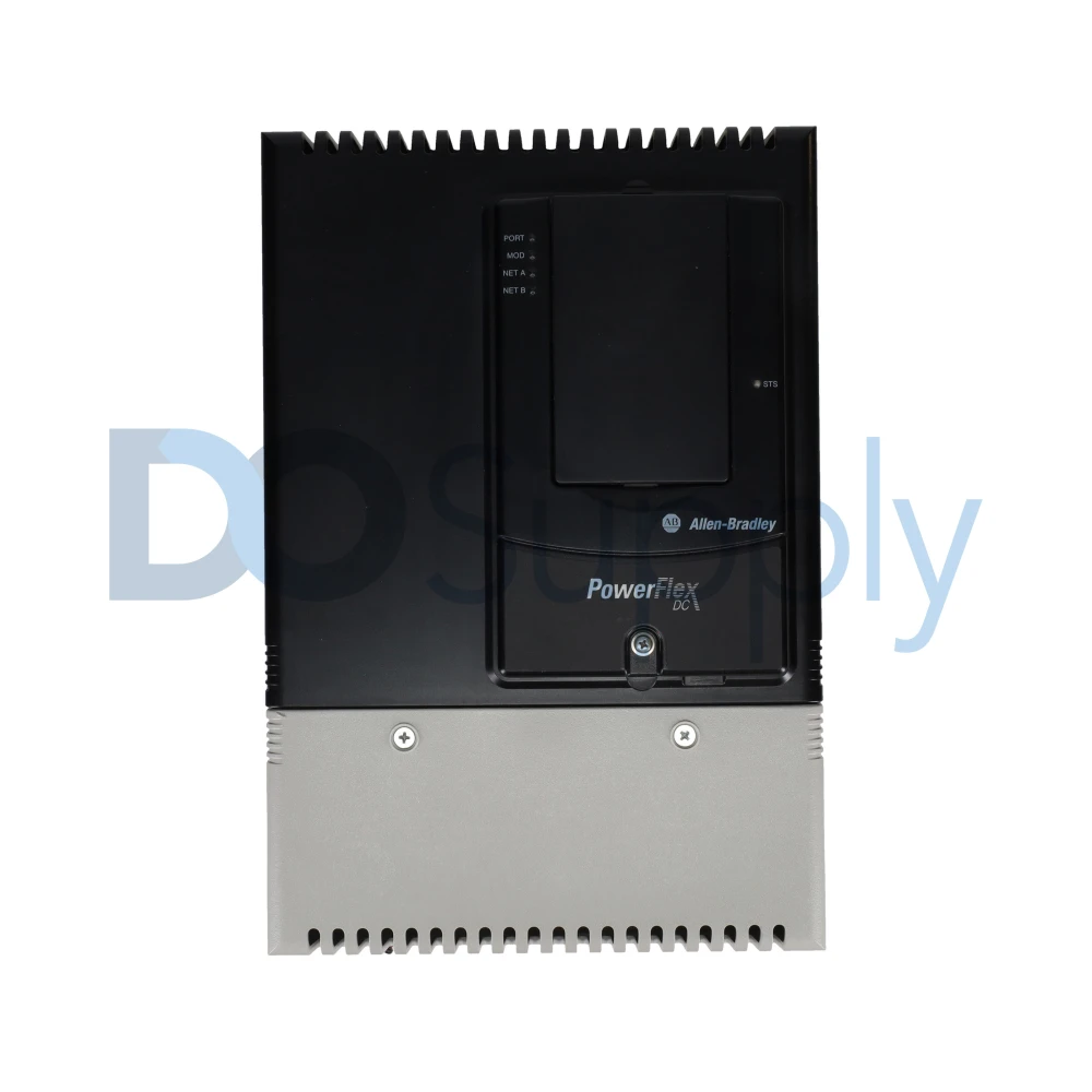
Non-regenerative drives are commonly one- or two-quadrant converters. A one-quadrant drive provides motoring torque in a single direction, such as forward motoring in Quadrant I. A two-quadrant drive can provide motoring and braking torque in one rotational direction, such as forward motoring in Quadrant I and forward braking in Quadrant II. Reversing motor rotation may require external armature contactors or another reversing arrangement.
Regenerative drives are true four-quadrant systems. Forward motoring, forward braking (generating), reverse motoring, and reverse braking (generating) are all smoothly handled by them. With recorded response times of less than three seconds for full direction reversal under regenerative control, this feature allows for quick reversing.
Power Circuit Topology: Hardware Architecture Comparison
The physical hardware architecture reveals substantial differences in component count and complexity.
A single unidirectional power converter bridge made up of six SCRs (Silicon Controlled Rectifiers) is typically used in non-regenerative DC drives. Only current flowing from the AC source to the DC motor is permitted by this straightforward architecture. External resistor banks must be installed for applications that need dynamic braking in order to dissipate energy during deceleration.
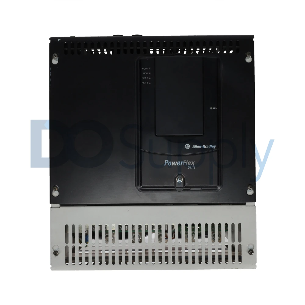
Two full anti-parallel power bridges with a total of 12 SCRs are used in common regenerative DC drives. While the second bridge controls regenerative braking and reverse operation, returning energy to the AC mains, the first bridge handles forward motoring. In order to avoid catastrophic short circuits between bridges, this dual-bridge system necessitates complex interlocking control circuits. The Generis drive platform is one example of a modern solution that uses proprietary switching technology to provide ultra-low harmonics with near-unity power factor and four-quadrant control.
Energy Management: Quantitative Efficiency Comparison
Energy handling represents the most significant operational differentiator with measurable financial impact.
Non-Regenerative Drives are unidirectional energy consumers. During deceleration, kinetic energy must be dissipated through external dynamic braking resistors when resistor-based dynamic braking is selected.
Bidirectional energy flow is achieved via regenerative drives, which return braking energy to the AC supply. Regenerative energy can be used internally by other axes in a multi-axis shared DC bus setup before being returned to the line. For example, the KEB R6 line-regeneration unit connects to the DC link used by frequency inverters and feeds excess DC-bus energy back to the line. Although this is not the same architecture as a traditional regenerative DC motor drive, it demonstrates how recovered energy can be managed across a larger drive system.
Dynamic Braking: Technical Specifications and Requirements
The braking mechanisms differ fundamentally in both implementation and capability.
External dynamic braking (DB) resistors are necessary for controlled stopping in non-regenerative drives. Current passes between the DB resistance and motor armature during an emergency halt. At maximum motor speed, when the counter-electromotive force (CEMF) is greatest, the current is at its highest.
Without the need for external resistors, regenerative drives offer completely adjustable, closed-loop controlled deceleration. They provide smooth, customizable ramp-down stops while maintaining constant holding torque at zero speed.
Overhauling Load Management: Critical Safety Application
Handling overhauling loads, where the load drives the motor rather than the motor driving the load—represents a critical safety distinction.
A non-regenerative DC drive cannot return energy from an overhauling load to the AC supply. The system therefore needs another method of absorbing that energy, such as dynamic braking resistors or mechanical braking. Without an adequately designed braking system, speed control can deteriorate and mechanical brakes may experience greater wear and heat.
Overhauling load management is a specialty of regenerative drives. The drive automatically enters regenerative braking mode, delivering regulated negative torque to maintain accurate speed, when the load tries to accelerate the motor beyond its predetermined speed. When a loaded car descends, traction elevators with counterweights produce energy. With a regenerative drive, that energy is returned to the building’s power source instead of dissipating as heat.
Power Factor and Harmonic Performance
Power quality depends more on converter design than on whether a DC drive is regenerative. Traditional DC drives commonly use phase-controlled SCR bridges, which draw non-sinusoidal current and produce characteristic harmonics, especially the fifth and seventh in a six-pulse system. Their displacement power factor also worsens as the firing angle increases.
A conventional regenerative DC drive does not automatically solve these issues. Its dual SCR bridges allow power to flow back to the AC supply, but the drive can still produce harmonics and operate with a poor displacement power factor. Line reactors, harmonic filters, isolation transformers, or 12-pulse arrangements may still be needed.
Active-front-end regenerative systems perform differently. They can shape the incoming current, maintain near-unity power factor, and reduce harmonic distortion while allowing bidirectional power flow. These benefits come from the active-front-end design, not regeneration alone.
Cost Analysis: CAPEX versus OPEX
The financial profiles differ substantially across the equipment lifecycle.
Because they have fewer components, non-regenerative drives have a lower initial purchase price (CAPEX). However, lost braking energy and possible expenditures for external brake resistors and reversing contactors result in increased operational costs (OPEX). For non-regenerative systems, choosing a dynamic brake resistor necessitates careful sizing based on motor armature current ratings.
Regenerative drives normally have a higher initial cost because they require additional power-semiconductor hardware, current-direction control, bridge interlocking, and protection. The actual premium varies considerably with drive rating and system architecture. But the return on investment might be strong. Line regeneration units occupy a useful middle ground below around 50 HP: they are more powerful than brake resistors at a far lower cost and complexity than complete AFE systems. Calculations for energy savings are as follows:
- Energy per stop (Wh) ≈ Average regen power (kW) × decel time (s) ÷ 3600
- Annual savings = Daily kWh × operating days × electricity cost/kWh
A machine regenerating an average of 15 kW for 10 seconds, 100 times per day, over 250 operating days would produce approximately 1,042 kWh of gross annual braking energy. At $0.12/kWh, that energy would be worth about $125 before accounting for conversion losses.
Application Selection
The selection between drive types should follow a structured decision framework:
Non-Regenerative Drives are optimal for:
- High-friction or low-inertia applications
- Infrequent reversing requirements
- Precision stopping not required
- Simple conveyor systems, mixers, fans, and pumps
Regenerative Drives are ideal for:
- Frequent starting and stopping cycles
- Overhauling loads requiring controlled descent
- Energy recovery opportunities
- High-inertia machinery
- Elevators, cranes, hoists, downhill conveyors, winders
Decision criteria include braking frequency, presence of overhauling loads, multi-axis machine configurations, power quality constraints, panel heat limitations, and payback period calculation.
Final Thoughts
In conclusion, when choosing between regenerative and non-regenerative DC drives, application needs must be compared to budgetary predictions and quantitative performance indicators. For continuous-run operations with little advantage from energy recovery, non-regenerative drives provide simplicity, dependability, and a cheaper starting cost. Because of its greater dynamic control, increased safety for overhauling loads, and significant long-term energy savings, regenerative drives justify a larger initial investment. Regenerative technology is becoming the go-to option for demanding industrial applications because to its reported reaction times of less than one second, efficiency of over 90%, and compelling return on investment through recovered energy. If you would like to learn more about regenerative PowerFlex series drives, we have a blog post here that goes over the different regenerative drives, their technology, and what makes them special.
For both regenerative and non-regenerative DC drives, as well as other automation needs, visit us at DO Supply! We carry motion control components, PLCs, HMIs, and accessories to build cohesive automated solutions for your systems. Need help or are looking for something specific? No problem, our support team is ready to assist you in finding the right product for your needs!
DO Supply Inc. makes no representations as to the completeness, validity, correctness, suitability, or accuracy of any information on this website and will not be liable for any delays, omissions, or errors in this information or any losses, injuries, or damages arising from its display or use. All the information on this website is provided on an "as-is" basis. It is the reader's responsibility to verify their own facts.