Mastering Motion: A Step-by-Step Guide to Setting Up Your Kinetix 6200 Drive
The Kinetix 6200 Drive series is well known for its sophisticated motion control features, which provide accuracy, adaptability, and efficiency. It offers both standard and high-level motion control and seamlessly integrates with different industrial systems, making it one of the best choices for different automation environments.
The crucial steps for properly installing and configuring your Kinetix 6200 drive system are covered in this article. We will discuss input/output cable connections, power wiring, module installation, and system mounting requirements. We will go into detail on how to initialize the drive modules, assign node addresses, and create IP-based communication. You can guarantee the best possible performance, security, and dependability from your Kinetix 6200 Drive system by following these comprehensive instructions, which will also make the setup procedure go more smoothly.
Steps for Setting Up Your Kinetix 6200 Drive
Understanding the System Mounting Requirements
In mastering the setup of your Kinetix 6200 Drive, it is important to understand the system mounting requirements for best performance and safety compliance. Ensure that the drive system is enclosed in a grounded, conductive housing, meeting UL, CE, and UK standards, with an enclosure rated at least IP54 to prevent access by unauthorized personnel. For enhanced protection, a NEMA 4X enclosure exceeding IP66 is recommended. The mounting panel must be flat, vertical, and free from shock, moisture, and corrosive elements. Also, carefully size the enclosure to manage heat dissipation and adhere to power cable length limits to ensure system integrity.
Mounting of Modules
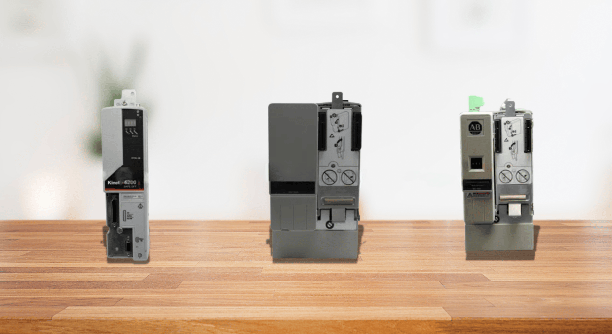
It’s crucial to adhere to specific instructions for a secure installation while mounting the AM, slot-filler, shunt, IAM, and IPIM modules for different Kinetix 6200 Drives. Because the voltage on these modules might be dangerous, first remove the cover from the power-rail connections, ensuring that the Power-applied indication is off. Turn the module down slowly, making sure the guide pins line up with the holes. Apply 2.20 Newton meters of torque to the screws to firmly hold it in place.
Understanding of the Input Power Configurations
Choosing the right power arrangement for your drive system is essential before connecting the power (input) for the best performance. It is critical to comprehend the sort of power that your IAM-power module provides since it may operate in both ungrounded and grounded configurations. Ensure that every system component is safely and securely grounded for grounded power installations to reduce electrical noise. It’s crucial to make sure the system can function properly in ungrounded setups without a direct link to the ground, which may call for further isolation techniques.
In DC common bus designs, appropriate fusing is required to safeguard individual components when several modules share a single DC power supply. Always confirm the specifications for common bus fusing to prevent harm in the event of an overload. In some systems, setting the ground jumper is an important step that helps control grounding routes according to the kind of input power.
The modular drive system and power rail must also be grounded to the system subpanel for safety and optimal operation. If more than one subpanel is being utilized, make sure all are properly grounded to avoid any voltage differentials that can impair system performance. By following these instructions, you may minimize hazards, assure a safe and effective installation, and maximize the performance of your drive system.
Fulfilling Power Wiring Requirements
To guarantee safety and optimum performance, it’s crucial to adhere to certain power wiring specifications when connecting electricity to your Kinetix 6200 Drive system. To meet the drive’s heat requirements, copper conductors rated for at least 75 °C (167 °F) must be used in all wiring. The primary AC power’s phasing is arbitrary. Therefore, a particular sequence is not necessary. However, because it reduces electrical noise and guarantees system safety, a solid earth-ground connection is necessary for the system to operate safely and correctly.
Wiring the IAM/AM Modules
Start by connecting the IAM/AM module connections according to the normal power wiring instructions. As the Control Power (CPD) connection supplies the module with control voltage, make sure it is wired appropriately. To power the drive system, the Input Power (IPD) connection needs to be wired according to the voltage and current specifications that are particular to your installation.
Specialized Connectors
The Contactor Enable (CED) connection regulates the contactor’s ability to be enabled or disabled to safeguard the system against power outages or other disruptions. The Motor Power (MP) connector, which provides power to the motor attached to the drive, must also be wired.
In resistive brake applications, the motor/Resistive Brake (BC) connector needs to be connected properly to regulate braking energy and provide appropriate stopping control. Following these comprehensive power wiring instructions will securely power and activate your Kinetix 6200 Drive system.
Input and Output Cable Connections
The Kinetix 6200 Drive system must have feedback and I/O cable connections done correctly for it to function accurately. To provide accurate control, begin by connecting motor feedback utilizing flying-lead feedback cables and pinouts. Panel-mounted breakout board kits provide more connectivity possibilities, and pre-molded motor feedback cables make installation easier. Low-profile connection kits can be utilized for further versatility. Secure connections are necessary to control power dissipation and guarantee effective operation for external shunt modules, IPIM, and RBM modules. Furthermore, connections can be established using Sercos fiber-optic and Ethernet cables to facilitate dependable data transfer and system integration.
Configuring the Drive Modules
Setting the Node Address of the IAM/AM Modules
Setting the address on a particular node on the IAM power module is the initial step toward the module’s configuration. This determines each linked control module’s node address. To begin with, make sure that any sort of power modules are unplugged and check that the communication-based wires are connected correctly. You can use the “Node Address switches” to set the base node address. Valid addresses range from 001 to 254, with the left switch controlling the MSD and the right switch having control of the LSD. Communication over an EtherNet/IP network requires this address.
IP-Based Control Module Addressing
The base node Address assigns the IP address of the IAM module, which also establishes the addressing for other control modules that are placed on a similar rail. The IP address of this particular module will be http://192.168.1.1, for instance, assuming that the 001 is its base node address. Subsequent control modules will increase from that IP address. The IP address of each new module rises consecutively, simplifying system configuration.
Initializing and Testing the System
To initialize the module, cycle the control power after configuring the node address. Check the IAM and AM control modules’ node addresses as they move across the four-character display. Configure the Logix controller, the motion group, and the EtherNet/IP module after the node addresses have been set up correctly. After everything is configured, launch the application, turn on the machine, run some tests to make sure everything works smoothly, and then adjust the axes for the best results.
Conclusion
In conclusion, setting up your Kinetix 6200 Drive system involves meticulous attention to system mounting, module installation, power wiring, and input/output connections to ensure optimal performance and reliability. In conclusion, to achieve optimum performance and dependability, carefully consider system mounting, module installation, power wiring, and input/output connections while configuring your Kinetix 6200 Drive system. Install the system in a grounded enclosure following the instructions, use copper conductors rated for 75 °C (167 °F) for power wiring, and correctly establish node addresses for EtherNet/IP connection. Assemble feedback and I/O cables securely, and make sure all wiring connections—power, control, and braking—are made. Complete the configuration by initializing modules, cycling control power, and running thorough tests to confirm system operation. You can make sure the drive system runs safely and effectively and provides accurate motion control for your industrial applications by closely adhering to these rules.
Here at DO Supply we specialize in Allen Bradly PLCs and Drives. While this blog post aims to help with the general installation practices, if you need help setting up your Kinetix drive or even ordering more for your applications, please feel free to give us a call or send an email and our team of techs and sales representatives will happily reach back out. If you would like to read more on the drives we carry, this article here on features that you may not know about Allen Bradley drives might interest you.
DO Supply Inc. makes no representations as to the completeness, validity, correctness, suitability, or accuracy of any information on this website and will not be liable for any delays, omissions, or errors in this information or any losses, injuries, or damages arising from its display or use. All the information on this website is provided on an "as-is" basis. It is the reader's responsibility to verify their own facts.