A Step-by-Step Guide to Setting Up Your Kinetix 6200 Drive
It is important to follow the correct procedure for setting up your equipment, especially servo motors and actuators. Not only does it enhance your understanding of the piece you are using, but it also optimizes performance. Following are detailed instructions for setting up your Kinetix 6200 drive. It summarizes the official manuals for installing power and control modules. It also highlights their integration with the Logix5000 controllers and adhering to safety protocols to ensure an efficient and safe installation.
Understanding Power and Control Modules
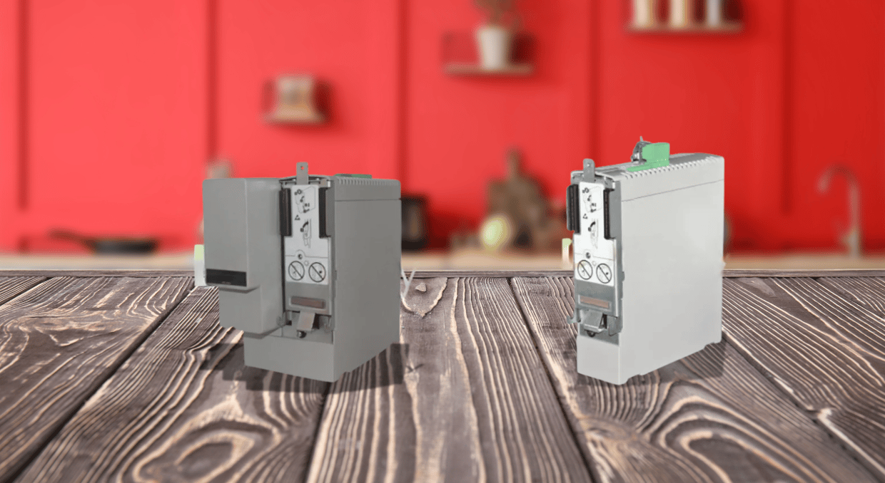
The Kinetix 6200 drive system consists of a power module and a control module. These modules operate in tandem to manage and drive motors. Integrated Axis Module (IAM) and Axis Module (AM) power modules are two key components.
- The IAM Power Module is the primary power module. It supplies power to connected motors and actuators. It is installed at the leftmost of the power rail. This ensures that alignment is proper for better functionality.
- The AM Power Module is responsible for supporting additional motors and actuators. This expands the system’s overall power management. There can be as many as seven AM Power modules connected to a system. This allows for versatility in large scale operations.
Each IAM and AM power module requires a corresponding control module to function. The control module dictates how the power modules communicate with external controllers. This allows for real-time monitoring and diagnostics with either Sercos or EtherNet/IP protocols depending on the variant of the control module. The Sercos is used to communicate with the Logix5000 controller, while the EtherNet/IP is used to access the safety configuration tool. Depending on your setup, you’ll use safe torque-off or safe speed monitoring functionality.
Installing Power Modules
Before you start with the installation of the power modules, begin by preparing your mounting panel, and securely affixing the power rail using Bulletin 2094 mounting brackets. The power rail supports up to eight modules.
Module Installation Sequence:
- The IAM module supplies power to all the connected modules, so it must always be installed in the leftmost slot of the power rail. Once it is positioned, the AM and IPIM modules are to be placed to the right, following the order from the highest to the lowest power utilization.
- If there are fewer than eight modules, 2094 slot-filter modules are used to occupy the empty slots on the power rail. This ensures the system’s integrity and prevents dust or debris from entering the unoccupied slots.
To install the power modules:
- The protective covers are removed from the power rail to expose mounting guides.
- The IAM power module is then aligned with the guide pins on the rail.
- The module is gently pushed until it clicks into place. The click ensures a proper connection.
- The mounting screws are finally tightened to a torque of 2.26 N•m (20 lb•in).
The same procedure is repeated for each AM or slot-filter module. This is the correct installation method, and it stabilizes the operation and prevents misalignments or interruptions in power flow.
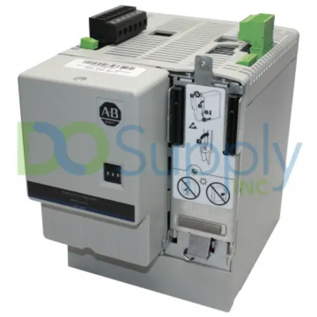
Installing Control Modules
The control modules can be mounted, once the power modules are installed. The Control modules manage motor feedback, user I/O, and auxiliary feedback signals.
To install the control modules:
- Firstly, it is made sure that there is no input power to the IAM module by checking that the power-applied indicator is off.
- The control module is aligned with the guide pins and hooks on the power module.
- The control module is pivoted to connect it securely with the power module’s signal connectors.
- The control module is fastened in place using the captive screw.
The process remains the same for each control module corresponding to the IAM and AM modules. After all the modules are mounted firmly, an integrated system is formed. It is capable of efficient motor control and feedback communication. It is to be kept in mind that improper or loose connection might lead to issues related to operation or even communication failure.
Safety Considerations
General safety precautions are officially prescribed when installing or servicing the Kinetix 6200 system. Following an adequate procedure reduced the risk of injury or equipment damage. Following are some of the key safety hazards highlighted in the Kinetix 6200 installation manuals.
- Shock Hazard: Since the Kinetix 6200 system operates at high voltage, coming into contact with live electrical components can cause serious injury. It is a good practice to always disconnect power before installing or servicing any module.
- Burn Hazard: Some surfaces of the power modules can become extremely hot during operation. All modules should be carefully handled and allowed adequate cooling time after shutdown before any surface is touched.
- Arc Flash Hazard: Electrical systems with high voltage can produce arc flashes, which could be fatally risky. Personal Protective Equipment (PPE) must always be used when working with electrical components, including gloves, eye protection, and flame-resistant clothing.
For the installations that use ungrounded power configurations, the grounding jumper in the IAM module must be set correctly. Following are some steps to ensure the jumper is correctly adjusted:
- The IAM module is removed from the power rail
- The grounding jumper is changed to the correct setting based on the environment of the installation.
- The IAM is then installed again securely in its original position.
Integration with Control Systems
The Kinetix 6200 system can be integrated with Allen-Bradley’s Logix5000 family of controllers. These include ControlLogix, CompactLogix, and SoftLogix. As stated previously, the drive system can use either sercos-based or EtherNet/IP-based control modules depending on your communication needs.
- Sercos-based modules offer high-speed data exchange for precise motor control and feedback. They are integrated with Logix controllers to provide deterministic, real-time communication.
- EtherNet/IP-based modules are ideal for systems where safety is critical. They allow for additional safety features such as STO, and SSM. These features are programmable via the Logix5000 configuration tool.
If properly integrated with the control system, the Kinetix 6200 drive can ensure that the system operates at its maximum efficiency, and the built-in safety protects both personnel and equipment.
Conclusion
The installation process for the Kinetix 6200 drive system requires attention to detail. By following the step-by-step instructions provided in this guide, you can ensure that the drive system is set up efficiently and safely. The guide covers everything from power module placement to control module installation and critical safety measures. Proper integration with Logix5000 controllers guarantees optimal performance and reliable results for your servo motors and actuators. Looking to simplify your Kinetix 6200 drive setup or need expert advice on your industrial automation needs? Here at DO Supply, our dedicated team is ready to help you find the right solutions, whether you’re upgrading your system or troubleshooting existing equipment. Visit us at DO Supply today and let us make your installation process seamless and stress-free. Or if you would like to read up more about the Kinetix series drives, this article going over the entire Kinetix 6000 line might just be up your alley.
DO Supply Inc. makes no representations as to the completeness, validity, correctness, suitability, or accuracy of any information on this website and will not be liable for any delays, omissions, or errors in this information or any losses, injuries, or damages arising from its display or use. All the information on this website is provided on an "as-is" basis. It is the reader's responsibility to verify their own facts.