Getting Started with the Allen-Bradley SMC-2: Your Step-by-Step Guide
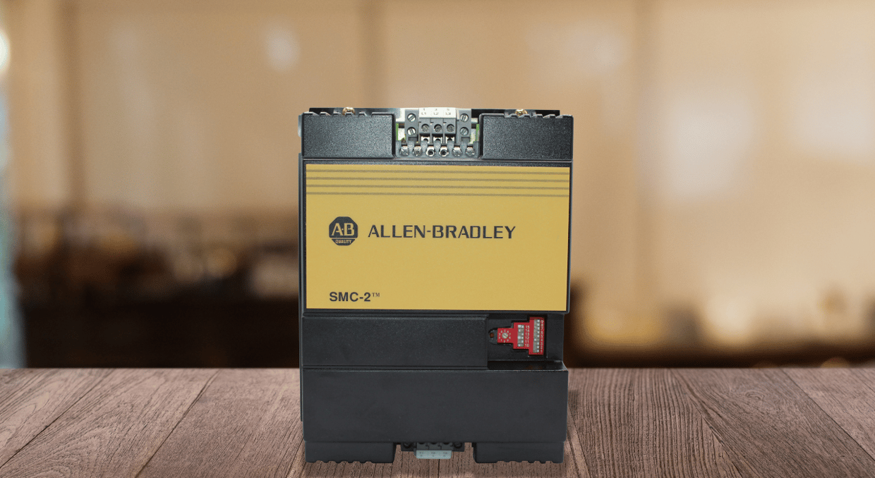
The Smart Motor Controller SMC-2 from Allen-Bradley is designed to control and protect motors, making it applicable in various industrial applications. Essentially, the device allows one to operate motors rated at 24A, 35A, 54A, 68A, or 97A by facilitating soft start, current limit, or full voltage start. Here are the essential installation and configuration steps to get you started with the device and ensure it fully meets your operational needs.
Understanding the SMC-2 Smart Motor Controller
Understanding the installation and setup is incomplete without knowing the key features and specifications of the SMC-2. The controller is designed for different motor HP and kW ratings based on the current rating. For example, a 24A controller can handle a motor load of 460V up to 15 HP, while a 97A controller can support loads of up to 75 HP at the same voltage. This drive can be ordered with an open chassis, in a NEMA Type 4 (IP65) enclosure, or a NEMA Type 12 (IP64) enclosure, depending on the specific environmental conditions. It is worth noting that the enclosure type depends on the specific catalog number and the application requirements. The input line voltage to this drive can range from 200- 240V to 500- 600V, with an operational frequency of either 50Hz or 60Hz.
Key Features
- Soft Start: Gradually increases the motor voltage, reducing mechanical pressure and electrical surges during startup.
- Current Limit: Limits the maximum starting current, making it suitable for applications with current constraints.
- Full Voltage Start: Offers an accelerated, across-the-line start in applications that demand an immediate maximum power connection.
- Energy Saver: Minimizes energy consumption when the load is light.
- Stall Protection: Detects and reacts to motor stall conditions, thus preventing any damage.
Installation and Wiring
Inspection and Enclosure Guidelines
Before installation, inspect the controller for any damage that may have occurred during shipping or handling. If damage is noticed, a notification should be issued to the carrier.
With open-style devices, ensure that the enclosure has sufficient space for ventilation. For instance, a Minimum NEMA 1 vented enclosure with a 142 cm² (22 in²) vent area is required for a 24A controller. Additionally, larger 68A and 97A controllers require more than this, with 100 CFM or more of additional ventilation, such as a fan.
Mounting the Controller
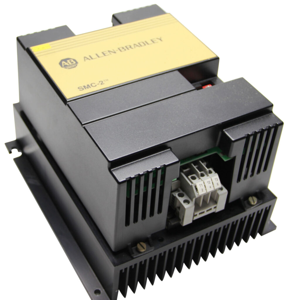
The SMC-2 controller has convection cooling, so the mounting position is also relevant: it should be installed with the heatsink fins in a vertical position. It is essential to ensure that the unit allows free airflow between the upper and lower sections.
Wiring the Controller
Wiring should be carried out by connecting the line to terminals L1/1, L2/3, L3/5, and the load to terminals T1/2, T2/4, and T3/6. To ensure grounding, the heatsink should be connected to an earthing and bonding terminal that has been installed in the field. Additionally, tighten the connection using the correct wire size and recommended tightening torque found in the manual. For example, the power connections for digital controllers 24A require an 18-gauge wire (AWG) and a torque of 1.6 N-m (14 lb-in).
To power the 97A controllers’ heatsink fan, there is a 45VA capacity gap. The fan jumpers are configured for 110/120V AC by default, but it is possible to change them to 220/240V AC.
Wiring with Interface Option
There are optional extra wiring options that can be used with the SMC 2 controller for the interface. The interface module has three control wires; the start and stop buttons are connected to terminals 10 and 30. The NEMA rating for the auxiliary contact is C300, 2.5 Amperes at 20 – 250 Volts AC or one Ampere at 12 -30 Volts DC.
Isolation Contactor
If the operator has switched off the controller, it is advisable to use an isolation contactor to ensure electrical isolation. This is necessary for securing the device and personnel safety, since dangerous voltages can remain at the load terminals when the controller is powered off. The isolation contactor must be installed according to the diagram in the manual.
Set-Up Procedures
Start and Stop Sequences
- The SMC 2 can work in two modes: without the interface option, also known as series controller mode, and with the interface option or 3-wire control mode.
- Without Interface Option: The controller starts automatically when power is applied to the line side and stops when power is removed.
- With Interface Option: The controller is set in manual mode and can be operated by pressing the start and stop buttons. The interface option also enables soft stop functionality, which gradually reduces the motor voltage during shutdown.
Overload and Fault Trips
The SMC-2 can identify several malfunction situations, such as short-circuited SCRs, motor stall, and phase loss. If there is a malfunction, the controller shuts down, and an indicator light on the front panel will flash red. Overload trips are handled by the overload relay, which should be correctly coordinated with the motor’s amp rating.
Stalled Motor Protection
The controller is capable of detecting motor stalls during the starting and running modes. If the controller infers the stall condition during the starting phase, the system will shut down according to the selected ramp time. When a locked rotor state is detected, the controller will deactivate in four seconds during active operation.
Energy Saver
The energy saver feature helps reduce power consumption when the motor is facing a light load or no load at all. This feature can be enabled or disabled through DIP switch 7 present on the controller.
Configuring the SMC-2
Soft Start Configuration
Follow these instructions to set up soft start on SMC-2:
- Firstly, set the initial torque with the rotary digital switch (0-9 positions, corresponding to 0-70% of locked rotor torque).
- Second, alter DIP switches 13, 14, and 15 to configure the soft start time. (2-30 seconds)
- Third, enable the energy saver and stall protection using DIP switches 7 and 3, respectively.
- For the interface option, adjust DIP switches 1 and 2 to enable soft stop, and adjust DIP switches 10, 11, and 12 to set the stopping time.
Current Limit Configuration
For current limit mode:
- Turn DIP switch 8 to the ON position.
- Set the rotary digital switch to the desired current limit level (25-550% of full load amps).
- Adjust DIP switches 13, 14, and 15 to set the current limit start time (15-30 seconds).
- Enable the energy saver and stall protection features as needed.
Full Voltage Start Configuration
For full voltage start:
- Set DIP switch 9 to the ON position and ensure DIP switches 13, 14, and 15 are in the OFF position.
- Enable the energy saver and stall protection features.
- If using the interface option, configure the soft stop and auxiliary contact settings as required.
Troubleshooting and Maintenance
Common Issues
- LED Off: There are two possible reasons for this: either no three-phase power is available or the overload relay has failed. Proceed to look for the line voltage and overload relay.
- LED Flashing: In this case, the controller indicates a fault condition, such as a phase loss, a short-circuited SCR, or a stall. The first step is to inspect the motor and controller for any issues.
- Motor Does Not Accelerate: There can be a motor overload, low starting torque, or incorrect switch positions. Modify the start time and the initial torque.
Maintenance
Make sure each part of the protective module is inspected periodically for any apparent damage or discoloration. Ensure the power to the controller is cut before any maintenance work is conducted on the controller.
Conclusion
The SMC2 Allen-Bradley SMC-2 Smart Motor Controllers are essential for controlling the motor’s operations in an industrial environment. Following this guide will lead you through the steps of installing, configuring, and troubleshooting the SMC-2. With the SMC-2, it is possible to control the power flow to the motor, starting with soft start, current limit, or full voltage start.
We offer a variety of SMC2 models at DO Supply. Whether you’re in the market for a new one or want to repair an old one, we have you covered. Give us a call today and we can find just what would take your automation solution to the next level. We also have a comparison blog between SMC Plus and SMC 2 here, if you’d like to read more.
DO Supply Inc. makes no representations as to the completeness, validity, correctness, suitability, or accuracy of any information on this website and will not be liable for any delays, omissions, or errors in this information or any losses, injuries, or damages arising from its display or use. All the information on this website is provided on an "as-is" basis. It is the reader's responsibility to verify their own facts.