Understanding Torque Control vs. Speed Control in Industrial Applications
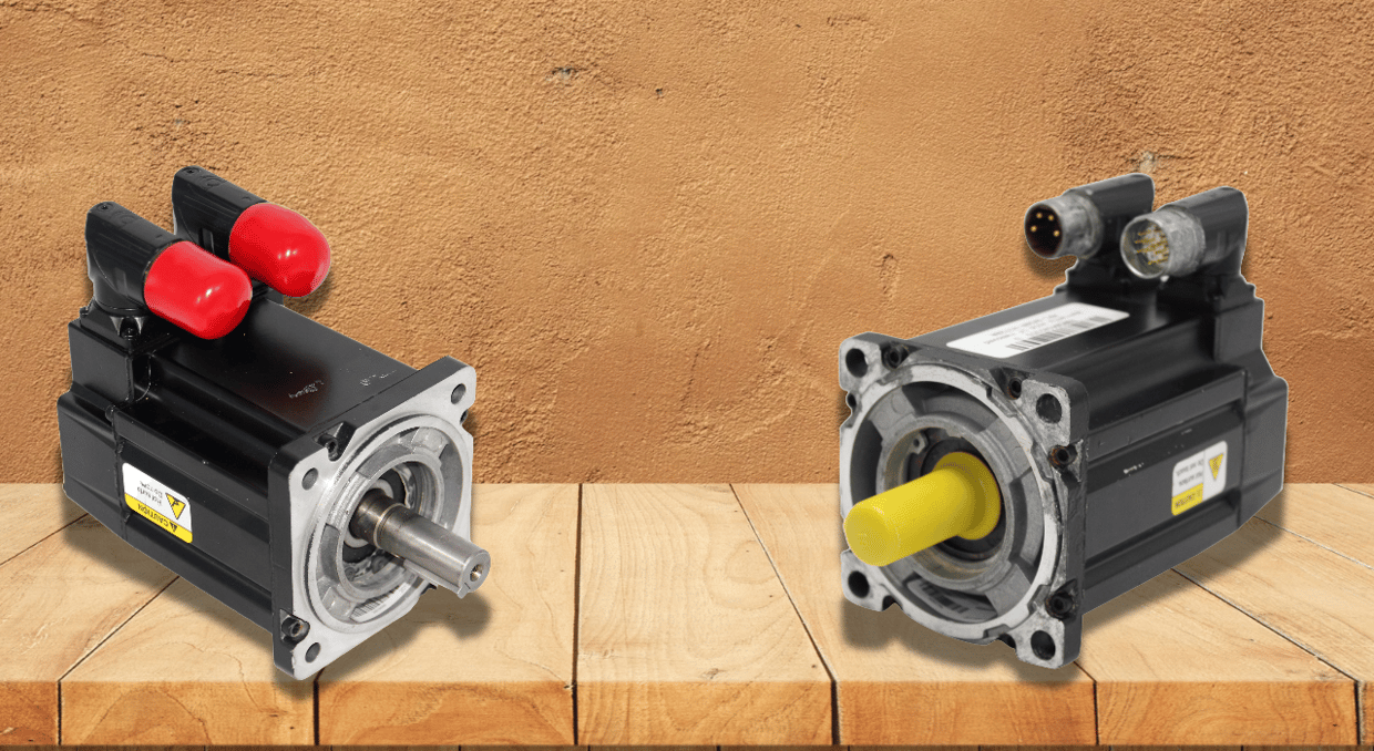
Speed control and torque control are the two main operating modes used by servo drives and variable frequency drives (VFDs) to run primary AC and DC electric motors. The drive’s internal control loops govern output voltage, current, and frequency based on the approach chosen under Torque Control vs. Speed Control system topologies. Torque control modulates active stator current to provide precise rotational force independent of speed variations, while speed control prioritizes maintaining the target shaft velocity regardless of load fluctuations. To implement the best control mode, we will analyze this article as Torque Control vs Speed Control, process stability, safety, and energy efficiency; system engineers must examine load characteristics, feedback devices, and mechanical dynamics.
Speed Control Loop Mechanics and Velocity Regulation
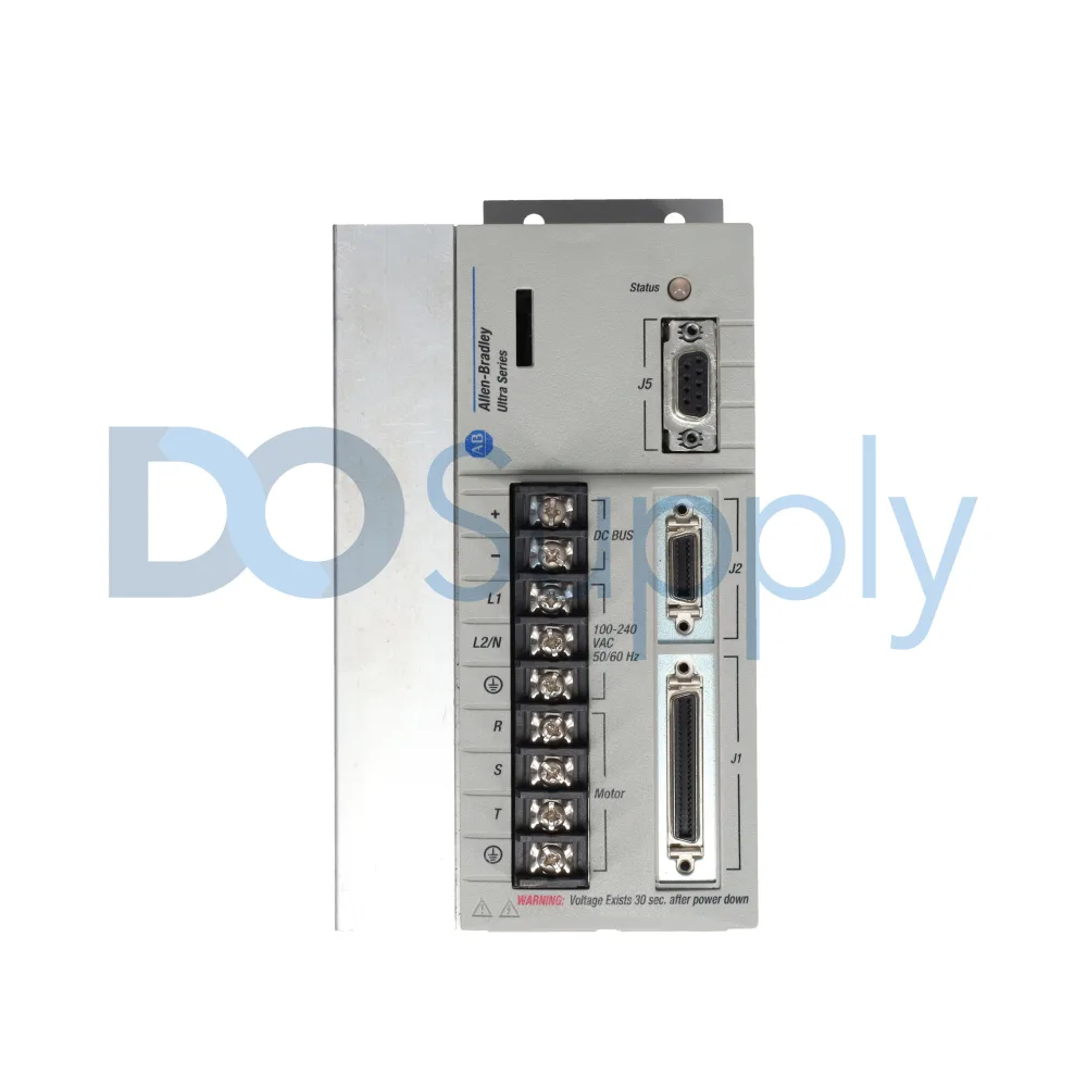
The motor drive operates as a closed-loop velocity regulator in speed control mode, with the inner torque reference being adjusted by the outer control loop while shaft speed is monitored. The drive uses sensorless mathematical estimates, absolute resolvers, or incremental encoders to compare the desired rotating speed with real data. To restore nominal RPM when an external mechanical load provides resistance, the speed controller detects the resulting negative speed error and increases quadrature-axis current (I_q). For industrial operations that need volumetric fluid discharge or continuous linear surface velocity despite fluctuating mechanical friction and load resistance, this mode is crucial.
Torque Control Loop Mechanics and Current Vector Regulation
In pure torque control mode, the drive provides exact electromagnetic torque by directly controlling the motor’s inner current loop and bypassing the outer speed loop. The drive decouples from flux current and controls the torque-producing current component using either Direct Torque Control (DTC) or Field-Oriented Control (FOC). In torque control implementations, the torque mode compels the motor shaft to produce precise mechanical force; actual rotational velocity thus depends entirely on the opposing load. Velocity stabilizes when load resistance matches the produced torque; as resistance decreases, the motor shaft accelerates until it reaches mechanical equilibrium or the drive’s overspeed thresholds.
Mathematical Foundations of Motor Power and Force Balance
In Torque Control vs Speed Control, the basic mechanical connection, which states that mechanical power is equal to torque multiplied by angular velocity (P=τ⋅ ω), is the basis for the operational physics guiding both control techniques. Power (P) scales linearly with load torque (τ) in speed control because velocity (ω) is maintained constant by varying current. In torque control, output power (P) scales in proportion to shaft speed (ω), but torque (τ) is set by clamping current. High-performance drives can sustain sub-millisecond torque response times without speed feedback because electromagnetic torque in AC induction and permanent magnet synchronous motors (PMSM) directly corresponds to the active quadrature current (I_q).
Torque Control vs Speed Control: Drive Architecture and Dynamic Response
| Technical Parameter | Speed Control Mode | Torque Control Mode |
| Primary Control Variable | Rotational Velocity (RPM / rad/s) | Active Shaft Torque (N ⋅ m / Current) |
| Active Loop Hierarchy | Outer Speed Loop drives Inner Current Loop | Direct Inner Current / Flux Loop execution |
| Reaction to Load Loss | Maintains setpoint RPM without acceleration | Rapid acceleration toward overspeed limits |
| Primary Industrial Objective | Continuous process throughput & timing | Material web tension & mechanical force |
Primary Industrial Applications for Speed Control Systems
Industrial automation systems that require consistent throughput, precise surface finishes, or stable volumetric flow rates for product quality depend heavily on effective speed control. To adhere to affinity rules and maintain system fluid head pressure, devices such as centrifugal pumps, industrial blowers, and dosing systems rely on precise speed management. To prevent product jams or fluctuations in gaps along assembly lines, synchronized surface velocities are essential for conveyor systems and automated material handling networks. Additionally, to sustain steady cutting speeds despite varying resistance from the depth of cut, CNC machine tool spindles, extruders, and rotary cutters utilize closed-loop speed control enhanced by high-resolution encoder feedback.
Primary Industrial Applications for Torque Control Systems
In converting, lifting, and material processing applications where regulating mechanical tension or clamping force is crucial, torque control mode is essential. Torque-controlled drives on take-up reels are used in paper mills, film slitting lines, and textile winders. The drive regulates torque proportionately to maintain consistent web tension and avoid material ripping as center-winder roll diameters increase.
To carry out torque-proving procedures, industrial cranes and mine hoists use torque control during mechanical brake release phases. This ensures that motor force balances the suspended weight prior to disengaging mechanical holding shoes. Bolt tighteners, metal stamping presses, and automated assembly machines use controlled torque limits to ensure proper fastening without damaging threads.
Master-Slave Coordinated Drive Topologies
In continuous material processing, complex production equipment often relies on simultaneous torque and speed control within master-slave drive configurations. The primary Master VFD in multi-drive web processing establishes the baseline production line velocity by operating in speed control mode. Meanwhile, secondary downstream slave drives precisely draw or wind the continuous web material with maintained tension in torque control mode, automatically following the master drive’s speed. This coordinated control prevents mechanical binding, gear backlash stress, and current looping across drives sharing a common load, thereby avoiding conflicts between coupled motors.
Dynamic Control Mode Switching Protocols
Dynamic mode switching is used by sophisticated industrial equipment to switch between torque and speed control at different stages of a single machine cycle. When the cavity fills, injection molding systems immediately transition to torque control mode (holding pressure) to pack the mould without going beyond mechanical strain limitations. Initially, the mould fills in speed control mode to inject polymer melt quickly. During web threading, industrial winders operate in speed control; once web tension is established, they smoothly switch to torque control. To avoid current spikes or torque bumps during loop reconfigurations, modern drive firmware uses bumpless transition algorithms to switch modes on the fly.
Safety Configurations and Runaway Prevention in Torque Mode
Because of Newton’s second law of rotation (α=τ_net/J), which states that unresisted torque induces fast acceleration, operating drives under pure torque control presents special operational dangers. If a mechanical shaft decouples or a material web breaks while operating in torque mode, the drive will continue delivering the target current, causing the motor to enter an instantaneous overspeed runaway. Torque-mode drive parameters must include internal speed-limiting windows (usually restricted at 105% to 110% of nominal RPM) to reduce mechanical risks. Furthermore, functional safety features such as Safe Torque Off (STO) and Safe Speed Monitor (SSM) physically stop drive inverter pulses under fault conditions or emergency stops.
Engineering Criteria for Drive Control Mode Selection
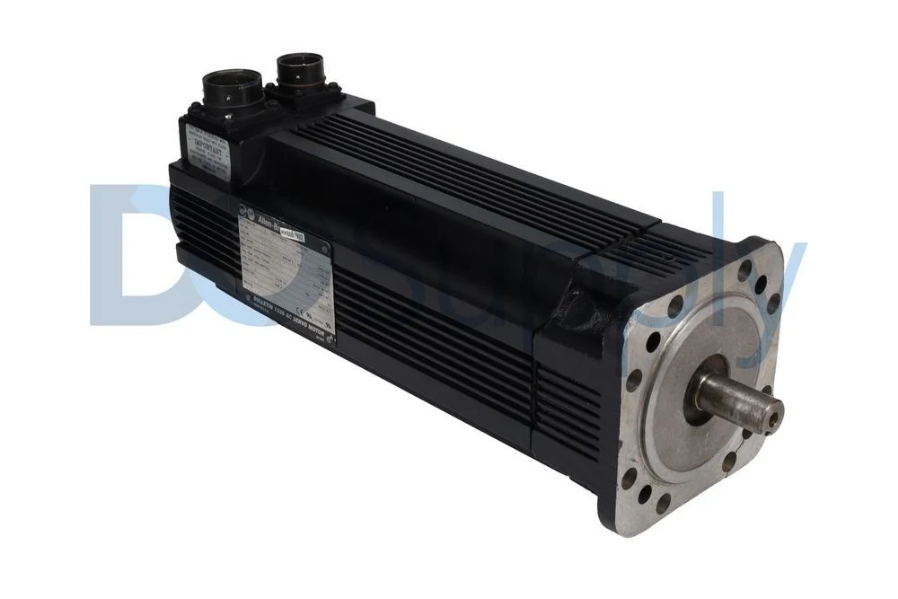
A thorough analysis of mechanical coupling, process feedback, and control goals is necessary when choosing between speed control and torque control. When exact timing, synchronized axes, or continuous linear transport are essential to process quality, engineers must implement speed control. On the other hand, when maintaining force thresholds, web tension, or load sharing across stiff mechanical connections is essential to system integrity, torque control is required. Auto-tuning motor stator resistance, leakage inductance, and moment of inertia parameters is necessary for proper drive commissioning in order to guarantee that field-oriented control loops perform both torque control and speed control with the best possible dynamic stability.
Energy Efficiency and Thermal Management Considerations
In Torque Control vs Speed Control, system heat losses, mechanical stress, and total power consumption are all directly impacted by the operating mode chosen for a variable frequency drive.
- Speed Control Efficiency: Affinity rules, which state that power consumption grows cubically with speed (P∝n^3), are used by drives operating centrifugal loads (fans, blowers, pumps) in speed control mode. When compared to mechanical throttling, a 20% speed reduction results in a roughly 50% reduction in energy use.
- Torque Control Thermal Realities: Rapid heat buildup occurs in the stator windings and rotor bars when a motor is operated under torque control at low RPM or stopped under full rated torque. Torque-controlled motors working continuously throughout wide speed ranges need external forced-ventilation cooling units (separately driven blower fans) to avoid thermal insulation breakdown since internal cooling fans linked to the motor shaft lose efficacy at low speeds.
Final Thoughts
In conclusion, considering torque control vs speed control, whether an industrial process needs accurate mechanical velocity or regulated rotational force determines whether driving strategy, torque control or speed control, is best. For devices like conveyors, pumps, and CNC spindles that need constant throughput, accurate timing, and consistent flow rates, speed control is still the industry standard. On the other hand, torque control is crucial for applications like winders, hoists, and automated fastening equipment that are focused on material integrity, tension management, and force application. System engineers can maximize process performance, avoid mechanical wear, and guarantee operational safety in complex automated environments by utilizing sophisticated control algorithms like Field-Oriented Control (FOC) and Direct Torque Control (DTC), master-slave architectures, and dynamic mode switching.
If you are in the market for automation equipment, let us at DO Supply be your one stop shop for sourcing PLC’s, HMIs, VFDs, motors, and everything in between. We stock parts from popular brands, such as Allen-Bradley, Mitsubishi, Omron, and more. We also provide repair services for faulty equipment backed by our two-year warranty. Give us a call today!
DO Supply Inc. makes no representations as to the completeness, validity, correctness, suitability, or accuracy of any information on this website and will not be liable for any delays, omissions, or errors in this information or any losses, injuries, or damages arising from its display or use. All the information on this website is provided on an "as-is" basis. It is the reader's responsibility to verify their own facts.