What do Capacitors do in VFDs?
VFDs or Variable Frequency Drives are controller systems including motors that give varying output speed as per input command. The capacitor forms DC links the whole VFD system. The voltage across this DC link is an important parameter to be controlled. This voltage is input to the inverter and thus acts as a reference voltage in the system. Variations in DC link voltage or voltage across the capacitor impacts the speed and performance of motor greatly. The selection of capacitor is equally important as its size will define the ripple factor, noise, and smoothness in the running of the motor. While it is important to know the significance and working of capacitors in a drive system, let’s understand the basics of the drive system, associated terminologies, and common topologies.
To understand the purpose of capacitors in VFDs, one should have an idea of the purpose of VFDs and their basic work topology.
What are VFDs for?
Variable Frequency Drives are electromechanical systems in which the speed and torque of a motor are varied as per input command. Such electromechanical systems are of high importance for industrial, commercial as well as domestic use. Their use is diversified in applications ranging from mining to packaging, pumps to blenders, and washing machines to fans. Applications involving VFD systems demand the accuracy of their operation as well. For example, the user wants the elevator to be stopped at any specific floor with its bottom aligned with that floor. Accurately controlled VFD system has to ensure that motor moves enough to bring elevator at that level, neither above nor below the floor level. Here, the motor speed will be adjusted for some time to attain that previously known position. Similarly, in the mining industry, the drill should move finely towards a targeted place and drill through – not more or less than the desired depth. Here, the speed of the drill (apart from position) and thus motor will also matter depending upon material hardness.
The Positioning of a Capacitor in a Variable Frequency Drive (VFD) / Basic Structure of a Variable Frequency Drive (VFD)
A drive system is composed of a few sub-systems or components. The three main parts are the control part, electronics part, and electrical machine.
The electrical machine is the key component of an electromechanical system whose motion is to be controlled. Sometimes, just an electrical machine is misunderstood as the whole drive. Selection of machine in a Variable Frequency Drive system involves many factors like application, cost, environment, available controller technology, etc. Mainly, induction machines are used as three-phase motors because of their low cost, rugged structure, and low maintenance need. Anyhow, for high-end applications (where low weight and higher torque density are valued; and high cost is not a point of concern), permanent magnet motors are used. These permanent magnet motors could be surface permanent magnet motors (SPM) or Interior Permanent Magnet Synchronous machines (IPMSM). PM machines have relatively simple controllers mainly because the direction of flux is a known parameter due to the presence of magnets. Now, reluctance motors are also being explored which have rugged structure as well as low cost. These motors bring only reluctance torque into use. Anyhow, controllers for these motors are not mature yet. Noise in the motor is another major problem for these machines.
The controller is one of the three main subsystems in a drive system that is equally crucial. It is given reference values, fed with real-time measured parameters to generate control signals for switches in the electronics part. The controller can be built as an open-loop control system (volt hertz controller) or a closed-loop control system. Closed-loop controllers are complex and have a wide range. These controllers could be PI (proportional and integral) or PID (proportional, integral, and derivative) controllers. Control parameters could be developed in ABC or QD reference frames depending on the availability of sensors, and the complexity of control loops. Complex vector controllers are also trending for more precise control in transient as well as steady-state phases. Some applications allow one user to utilize open loop or basic closed loop controllers. But for others, complex vector controllers are preferable.
Electronics or power electronics part of a drive system is a system in itself. The capacitor is one of those components. Before the placement of the capacitor, an AC/DC converter or rectifier is built. After the capacitor or DC link, an inverter is used which converts DC to AC. The legs of both AC/DC converter (rectifier) and DC/AC inverter are built using switches that are turned on and off by control signals generated by the controller part. These switches could be MOSFET or IGBT switches.
Once, the whole structure of a Variable Frequency Drive is understood and linkage between different parts is established; the basic topology of a drive system is shown to know the placement of capacitor in this structured system.
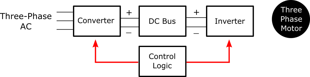
In this block diagram, the converter receives 3 phase AC signal from the main grid and gives output in the form of a DC signal. This DC signal is stabilized by a DC bus which comprises a capacitor (a component of concern) and a filter. Stable DC signal – output of DC-link or DC bus is fed to the inverter input terminals. The inverter converts DC into AC which runs three phases electric motor. Control logic is developed in the controller part. Signals, generated from the controller, control switches both in the rectifier as well as an inverter. Black lines in the block diagram show flow of electric signals while red lines show the flow of control signals.
Why Use a Capacitor in a VFD?
As drive systems are used for motion applications (related to position and speed) and motion of the motor is controlled by varying input frequency and voltage to the inverter. So frequency and voltage are control parameters. The voltage input to the motor is given by 3 phases of the inverter. As the inverter gets its input voltage from the DC link (voltage across the capacitor) so capacitor voltage is the reference voltage for the last stage (before it is fed to the motor) which needs to be stabilized for better performance of the motor. If there will be no capacitor, then what would one control? Rectifier output (inverter input)? But it will keep changing rapidly and hence controller will not reach any stable or steady-state solution.
Capacitor as a Filter
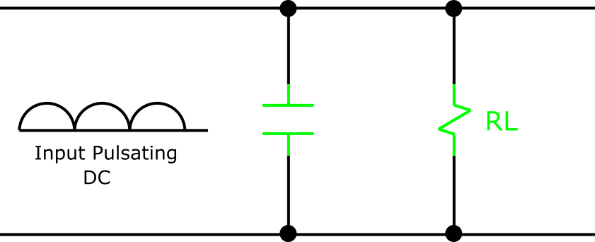
A capacitor, when used in parallel in the circuit across a load, works as a filter. The capacitor filters the AC signal completely. And glitches in the DC signal are also filtered by a capacitor. This is, conceptually, the same idea as explained above. The diagram below elaborates on this further.
Here, pulsating DC signal charges the capacitor rapidly initially. In the second half cycle of the input signal, the capacitor discharges through RL load. But notice the small size of ripple here than that of input signal ripple. A bigger capacitor will result in an even lesser ripple factor and a more stable signal.
If this concept is translated into the placement of capacitor in VFD, one can conclude that variation in grid signal would impact the rectifier output but not inverter input as filter circuit (capacitor or DC link) is placed between two blocks.
Can a Capacitor be Omitted in a VFD?
There is no direct yes or no answer to this question. Instead, we will assume the absence of the capacitor and analyze its effects on the result. If there is no capacitor, then the output of the AC/DC converter will go directly to the inverter. If the main supply from the gridline to the converter will dwindle, it means input to the inverter will dwindle. Despite the fact, that these parameters will be sensed (through sensors) and fed back to the controller (if there is a closed-loop controller), it would be too late to avoid ripple in the output waveform of the inverter. This ripple will cause noise in the running motor.
Furthermore, recall that drive is an electromechanical system in which the motion of an electric motor is of great concern. This motion translates into the position or velocity of some moving part in a specific application. So ripple in the motor input supply means, deviation from a demanded position or velocity trajectory. It infers that a Variable Frequency Drive system without a capacitor will be a poor drive system.
Work Mechanism of Capacitor in a VFD
Once it is established that a capacitor is a crucial component in a Variable Frequency Drive, it is yet to be explored how a capacitor performs this task in the system. A capacitor used in low and medium-voltage VFDs is an electrolytic capacitor generally. Such a capacitor, having two metallic plates in its structure and an electrolyte for insulation purposes, stores electrical energy in the form of an electric field between its two plates. A positive charge resides on one plate and a negative charge on the other and electric field lines are built up from the positively charged plate to the negatively charged plate.
Furthermore, capacitors have charging or energy storage capacity. When the charging process starts, the electric field builds up rapidly; the charging process slows down later, reaches its capacity, and stabilizes. Capacitor gets charged to two-thirds of its maximum limit within one time constant (the time constant is different for each circuit and depends on capacitance ‘C’ and resistance ‘R’ of the circuit). This is depicted in the figure below.
Generally, the charge storage capacity of a capacitor is far much than the charge coming along in a time (otherwise there would be no benefit of using a capacitor). If the same concept is applied to Variable Frequency Drives, it will be clear that capacitor placement and its capacity will affect transient response time. By the time, the transient response time will be over, the capacitor would also have been charged to the maximum of its capacity. So now the inverter will be getting a constant input value. Changes in grid voltage will not affect three-phase motor input if a capacitor of appropriate size would have been chosen.
Capacitor Size
The size of any type of energy storage electronic device impacts the performance of the whole system. For example, a larger inductor in the circuit will smoothen the current more. Likewise, a capacitor placed in parallel to desired voltage component will smoothen voltage. The larger the capacitor, the more smooth is the output voltage. But this benefit comes with a huge increase in cost. So, when a system is simulated to analyze the performance of a drive system, one must keep into account available capacitors and cost cap according to the sensitivity of the application.
Concluding Remarks
Discussion establishes that a capacitor is crucial in a drive system to attain output speed and motion trajectories as per the input demand signal. It eliminates prospects of uncertainties that could be caused by variation in the input signal from the main grid line. The voltage across the capacitor is DC link voltage and it is an important parameter to be controlled in a Variable Frequency Drive system. If this would be stabilized around desired value, then the output of the inverter will also be in a good 3 phase sinusoidal shape with appropriate rms (root mean square) and peak value. A good 3-phase output signal from the inverter will translate into desired motion pattern of the electric motor. It will allow VFD to work as per need.
DO Supply Inc. makes no representations as to the completeness, validity, correctness, suitability, or accuracy of any information on this website and will not be liable for any delays, omissions, or errors in this information or any losses, injuries, or damages arising from its display or use. All the information on this website is provided on an "as-is" basis. It is the reader's responsibility to verify their own facts.