Drive Component Overview: DC Bus Definition and Overview
Drive or Electric Drive is an electromechanical system that necessarily uses an electric motor or a prime mover. In this system, the motion of the electric motor is controlled to make it applicable and useful for some applications in the realm of industry, automotive, domestic use, hospitals, etc. In an electric drive system, energy conversion is controlled. Motor, control systems and power converter (power electronics) are major components of electric drive. The selection or construction of various drive components varies depending upon the application and environment where the system is to be used. DC bus is part of the power electronics part of the drive. Its stability and voltage control are crucial to gaining good results for the drive system.
Components of a Drive System
The Drive system is a complex electrical system. As mentioned earlier, the following are its major components
- Electric Motor
- Controller
- Power Converter or Power Electronics Section
These three components are complex systems in themselves. Variations in one or more of these components bring variety into the drive system. Selection of drive system from a whole range of variety depends upon cost, environmental suitability, durability, accuracy, precision, etc. All these components are discussed one by one in detail. It is also discussed logically which component will go well with which sort of application.
Electric Motor
The electric motor is such an important component of the drive system that, sometimes, it is mistakenly referred to as a whole drive system. Electric motors are widely grouped into these categories:
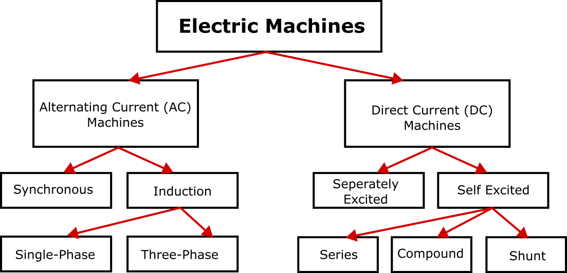
Direct Current or DC machines could be separately excited or self-excited. The control of electric drives and DC machines is quite easy. Technology has also matured for that of DC machines with regard to design, construction, as well as control. But DC machines have carbon brushes that undergo wear and tear. This brings in the need for regular maintenance. Moreover, with phase change, there is a fear of sparking. The output voltage from DC machines is also not sinusoidal. Due to all these reasons, DC machines are not used in high-end and sensitive applications.
Alternating Current or AC machines are used more widely for advanced drive systems. Here, these machines are elaborated more to keep readers up to date with trends in the field.
AC machines could be synchronous or asynchronous (induction). This categorization is made on the basis of phase harmony between rotor and stator fields. In synchronous machines, the rotor field is produced by a mechanism separated from that of the stator field mechanism. In other words, the generation of the rotor field does not depend majorly on stator winding or generation of the stator field.
In synchronous machines, the rotor could be equipped with permanent magnets, could have slits (refer to saliency), or winding for generation of field. Placement of magnets is the most common and efficient yet expensive way to a generation of rotor field. Orientation of magnets in these machines categorizes electric motors further into Surface-Mounted Permanent Magnet Surface Machines (SPMSM or SPM), and Interior Permanent Magnet Synchronous Machine (IPMSM). In SPM, as the name indicates, a permanent magnet is mounted over the surface of the rotor. This orientation is the reason behind the d axis (direct axis) and q axis (quadrature axis) inductances being equal. This factor makes the control of SPM relatively straightforward. In the case of IPMSM, the permanent magnet is buried inside the surface of the rotor. For these machines, the inductance of the direct axis is different from that of the quadrature axis. Permanent Magnet machines are more common in industries where weight and volume are concerning criteria because permanent magnets have quite high weight and volume density. So these motors are increasingly being used in the automotive industry which includes vehicles, marine, as well as aircraft industries. These machines are easy to control. They are highly reliable and efficient. The direction of flux is important in machine control. When a permanent magnet is there, the determination of flux direction is predetermined. This factor also contributes to the ease of machine control.
Synchronous machines with slits over the surface of the rotor are, basically, reluctance machines. These machines don’t have winding or magnets for the production of rotor fields. Instead, these slits provide a way for the production of the field. Machines make use of reluctance and electromagnetic torque. Reluctance machines bring into use the reluctance torque of electric machines only. These machines are also reliable because there is no winding on the rotor that could be damaged or no magnet attached to its surface. Generally, these machines have huge sizes because, for significant production of torque, there should be as many slits as possible. As the size is huge these machines so can be used for static applications. For example, for wind energy production, the use of reluctance machines in far-off places is increasing.
Non-synchronous or induction machines don’t have a mechanism for the production of rotor fields separately. In these machines, stator winding produces a stator field and this field is induced into rotor winding through an airgap. The rotor could be wound or have a cage rotor structure. Some time lag occurs as the field gets induced so rotor and stator fields are not in phase. For this reason, induction machines are also called asynchronous machines as well.
Controller
If the speed of the motor and thus the position of the rotor is not controlled, then the electric drive is of no use. For example
- If an electric motor installed in an electric vehicle goes at a constant speed or does not change speed as per the command of the driver, the vehicle becomes useless and dangerous.
- An elevator in a building needs to stop at a specific position so that its bottom gets aligned with the designated floor. But if control is poor and the elevator stops above or below that floor, the whole elevator system becomes useless and dangerous.
It can be said that an electric drive needs to have a good quality controller. A controller can be developed as an open-loop where there would be no feedback from the system into the system. Here, various assumptions would be made ignoring errors in the output and input. Anyhow, this open-loop or V-F control (also known as Volt Hertz control) is not preferred for high-end applications like automotive and packaging.
For accurate results in sensitive applications, closed-loop control is used. Closed-loop control refers to a control system where output is measured and compared with the input command to calculate the error. The higher difference means a higher error signal which leads to larger input causing the output to draw near to the input command. Previously, the closed-loop control system was developed in the ABC reference frame where the controller needed to track sinusoidal inputs. Three controllers were being developed which were slightly affecting one another. In advanced controllers, ABC reference frame control is not used now. Instead, reference frame transformations are made so that controllers are also developed in the DQ reference frame. Here, the advantage is gained from several perspectives
- The controller needs to chase steady-state values rather than sinusoidal signals.
- Two instead of three controllers are developed.
- Achieving zero steady-state error is possible now which was not possible in the case of ABC reference frame controllers.
- Need for a number of sensors and thus cost decreases accordingly.
- In this control technique, flux and current are easier to control. These two control parameters, one is controlled on the d axis and the other on the q axis. These parameters are not isolated completely but their interrelation is minimal.
Power Electronics (Power Converter)
The Power Electronics section is an interface between the motor and controller. The controller commands the signal and the power converter generates this signal by switching the electronic switches at a very high speed. This signal is fed to the motor, so it runs at the desired speed. Its speed or rotor position is measured or sensed so it could be feedback to get more precise results during the next time cycle. Phase currents and DC bus voltage is also measured through appropriate sensors. A generic block diagram of a typical electric drive system can be drawn as follows:
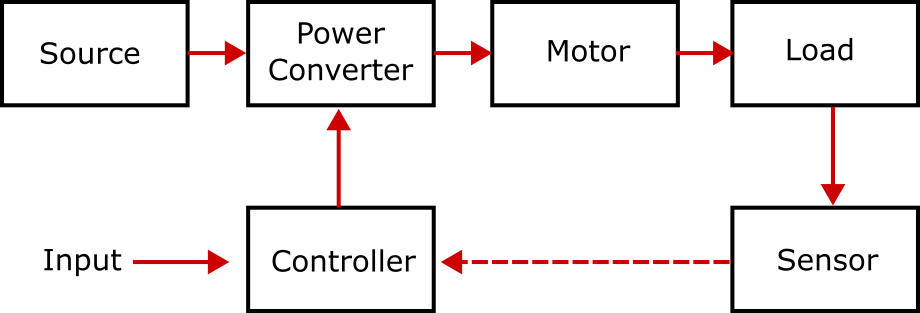
A thorough discussion has already been made on motor and controller sections. The power converter is expanded for the sake of discussion.
Three blocks in the middle, collectively, comprise the power electronics section. These blocks are named grid side converter, DC-link, and load side or motor side converter. As a standard, it is assumed that the grid is the source of power. Three-phase mains are not feeding the motor directly. All the circuitry between grid and motor paves way for speed and position control of the motor.
Grid side converter converts three-phase electricity into DC. So the first converter is a rectifier. The rectifier is connected with a capacitor that forms a DC link. DC link ensures that fluctuations in grid voltage will not impact inverter reference voltage and thus motor input voltage. The load side converter is DC to AC converter. It contains three legs and six switches. These switches are turned off and on repeatedly at high frequency such that the resultant voltage of each leg comes out to be sinusoidal. Dead time is introduced between switching two switches of the same leg so that there is no fear of shortening a leg. The pattern of switching for all switches is decided by the controller. Using PWM (Pulse Width Modulation) or SVPWM (Space Vector Pulse Width Modulation), gate signals are generated such that the output voltage of each inverter leg is maximum sinusoidal. The use of SVPWM makes the use of dead time unnecessary and minimizes switching loss significantly.
DC Bus or DC link
DC Bus is a circuit or mechanism that is to ensure stable voltage across its terminals. A high-value capacitor, generally, comprises a DC link. DC bus or DC link serves as an interface between rectifier and DC/AC converter in electric drives. Control of DC link voltage is crucial for the stable and desired performance of the electric motor. Among several sensors in an electric drive system, the voltage sensor is to measure DC bus voltage. Voltage measurement is taken to feed it to the controller.
DC link isolates input circuitry (grid side) from output circuitry (motor side) to some extent. The capacitance of the DC-link capacitor also plays a major role. It shouldn’t be too small that it becomes unable to perform purported tasks. It shouldn’t be too large to increase system costs rapidly without many gains.
DC Link Overview
DC link, in an electric drive, serves several purposes which are interconnected with one another somehow.
- For the traction motor to perform as per the input command, the reference voltage or input voltage for the inverter must be stable. Grid voltage can vary at any time causing motor speed to fluctuate. As grid voltage is never a control parameter for the user, the motor will never follow the input trajectory.
- Both grid side and motor side converters are designed using switches. As a switch turns on or off, harmonics other than that of basic harmonics are created. Switching of rectifier side switches would have impacted motor performance if the capacitor were not there. In other words, the capacitor of the DC link serves as a filter. The capacitor filters all AC signals.
- DC link voltage serves as a reference voltage which is controlled by controls systems so demanded input trajectory could be followed.
- DC link serves as an interface between the input side circuit and the output side circuit. It isolates two circuits to some extent so high-frequency changes are not felt on the output side.
- The size of the capacitor, being used in the DC link, sheds a significant impact. If its capacitance is too low that voltage difference across its terminals becomes comparable to rectified voltage then it will not serve as a good filter. If the used capacitor has very high capacitance then system cost will go up and initial charging would impact transient response also. So selection of capacitors is to be made carefully.
DO Supply Inc. makes no representations as to the completeness, validity, correctness, suitability, or accuracy of any information on this website and will not be liable for any delays, omissions, or errors in this information or any losses, injuries, or damages arising from its display or use. All the information on this website is provided on an "as-is" basis. It is the reader's responsibility to verify their own facts.