We found 92 posts about Maintenance from DO Supply, a global automation parts
reseller focused on hard-to-find and obsolete industrial automation products.
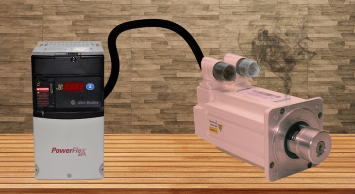
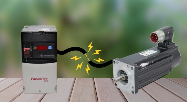
The most time-consuming diagnostic issue in industrial motor control is intermittent drive faults. Production halts, the drive trips, a technician resets it, and it runs for hours before malfunctioning again under similar circumstances. Since the drive is the most visible component and is showing the failure code, it is natural to blame it. Replacing the drive instantly restores production. The issue is that most persistent drive problems can be traced to external factors, such as loose power connections, deteriorated cable insulation, mechanical binding, supply voltage disruptions, or interference from control signals. A mechanical or electrical root cause, rather than a drive malfunction, often causes intermittent drive failure under the same circumstances. Effective drive fault research starts with understanding these external sources and the diagnostic methods that separate them. In industrial installations, loose connections are the second most common cause of drive faults. Heat...
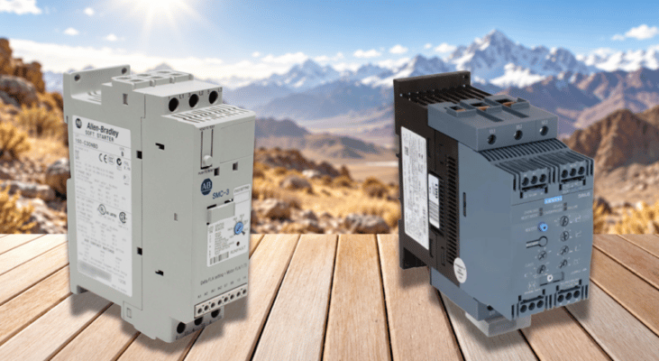
Every soft starter rating is based on a defined set of assumptions about ambient conditions, and those assumptions no longer hold once conditions change and the rated current can no longer be taken at face value. Specifying engineers and maintenance staff need to understand how ambient conditions interact with a soft starter’s thermal and dielectric limits in order to avoid nuisance trips, accelerated part wear, and outright failure. Manufacturer data from ABB, Siemens, Schneider Electric, and Rockwell Automation all point to the same underlying truth: a soft starter’s nameplate rating is a starting point, not a guarantee, once temperature, altitude, humidity, contamination, or vibration depart from standard test conditions. Understanding these factors is essential for correctly sizing and installing a soft starter in real-world operating environments. A soft starter’s current rating is assessed at a reference temperature; typically, this is 40 degrees C. This figure reflects the...
A failure history log is kept on file by all contemporary variable frequency drives. Every problem the drive has encountered is recorded, together with the precise operating parameters at the time of each trip: output current, DC bus voltage, output frequency, heatsink temperature, and, most of the time, a timestamp that puts each incident in chronological order. For a maintenance engineer in front of a stopped machine, this record is the most comprehensive diagnostic data source. In industrial maintenance, it is also the diagnostic tool that is most often disregarded. For example, the fault history is cleared before it can be read, or the reset button is pressed before data can be recorded. This article covers what drive fault history contains, how to interpret it properly, and why the quickest route from a tripped drive to a permanently fixed defect is to use it methodically. Most drives keep some form of fault history, but the amount of stored information depends on the model. This...
A variable frequency drive (VFD) rarely fails suddenly. Instead, before a VFD stops reliably operating a motor, it will begin to show signs of degradation, starting with symptoms like increasing fault counts, distinct noises, or thermal stress. These eventually culminate in signs of the drive’s aging internal components. If maintenance crews spot those early warnings, they may have time to install a new VFD before failure, keeping production running. A VFD’s service life is mainly controlled by two wear-limited parts with documented, temperature-dependent life expectancies: the electrolytic capacitor that forms the DC bus, and the cooling fan. Aging in both components is slow — they don’t fail on a fixed date but degrade gradually, so assessing age means understanding behavior, not just install date. ABB’s ACS550 documentation (page 67, section 4) and the ACSM1 VLT FC 302 documentation (page 4, section 2) describe this best. Electrolytic capacitors on the DC-link circuit smooth the...
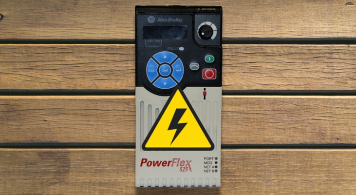
One of the most annoying diagnostic situations in industrial drive maintenance is a nuisance overcurrent issue. When the PowerFlex trips, production stops, the operator resets it, and it functions normally for many hours before tripping again for no apparent reason. Nuisance overcurrent faults are condition-dependent, sporadic, and seldom self-explanatory from the fault code alone, in contrast to a hard fault brought on by an obviously malfunctioning component. An overcurrent fault is a precise diagnostic signal intended to prevent damage to the motor, drive, and related equipment. It shows up as a strong, abrupt current spike that exceeds the drive’s hardware limits. Diagnosing any PowerFlex model, from the tiny 525 to the architecture-class 755T, depends on understanding what causes these spikes and distinguishing between hardware-level and software-level overcurrent detection. When diagnosing a PowerFlex overcurrent problem, the first thing to consider is whether the event is...
In PowerFlex variable-frequency drives (VFDs), the DC bus functions as the internal power bridge and electrical reservoir between the AC input rectifier and the output inverter stage. Once the incoming AC line voltage is rectified, the DC bus capacitors smooth and stabilize the resulting DC bus voltage by reducing voltage ripple, thereby delivering a steady DC supply to the inverter. They also temporarily absorb the regenerative energy produced during overhauling-load conditions or motor deceleration, reducing rapid voltage fluctuations and improving energy efficiency. This article provides a comprehensive overview of the fundamentals of DC bus voltage in Allen-Bradley PowerFlex drives. Knowledge of pre-charge drive operation, DC bus capacitors, shared DC bus configurations, DC bus regulation, regenerative energy management, and common DC bus-related faults enables engineers and maintenance personnel to maximize the reliability of PowerFlex drives, improve overall system performance...
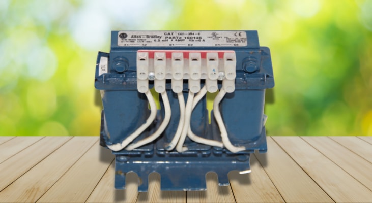
Modern motor control relies heavily on variable frequency drives, yet the components that safeguard them are often the first to suffer budget cuts. Line reactors, also known as input reactors, are often seen as optional add-ons rather than necessary safety measures. The electrical mechanics underlying reactor protection, the failure types that reactors avoid, and the cost justification for implementing them on each drive installation are all discussed in this article. In simple terms, an input reactor is a three-phase inductor placed between a drive’s input terminals and the incoming AC power source. Its purpose is surprisingly straightforward: it increases the line’s impedance. In a drive environment, this impedance smooths out the abrupt current spikes that occur each time the drive’s rectifier bridge charges its DC bus capacitors, as it resists rapid current changes. Drives convert incoming AC to DC using an SCR bridge rectifier or diode. Because the current is drawn in brief...
Teams with short timeframes set up Rockwell’s PowerFlex drives every day, and most of that work only touches the handful of parameters needed to make a motor spin: voltage, frequency, and a start reference. Once the motor turns, the commissioning checklist gets signed off, and everyone moves on to the next job. But PowerFlex drives feature dozens of secondary parameters that regulate efficiency, thermal load, fault tolerance, and lifespan. When these are left at their defaults and never reviewed, the drive still runs, but often well below its capabilities. Factory settings on a PowerFlex drive exist for one reason: broad compatibility. They are built to work across a wide range of motors and applications, which means they are rarely ideal for any single fixed installation. A default acceleration ramp, carrier frequency, or stall timer is enough to get a drive running. Still, it won’t match the thermal properties of a specific motor, the inertia of a specific load, or the electrical...
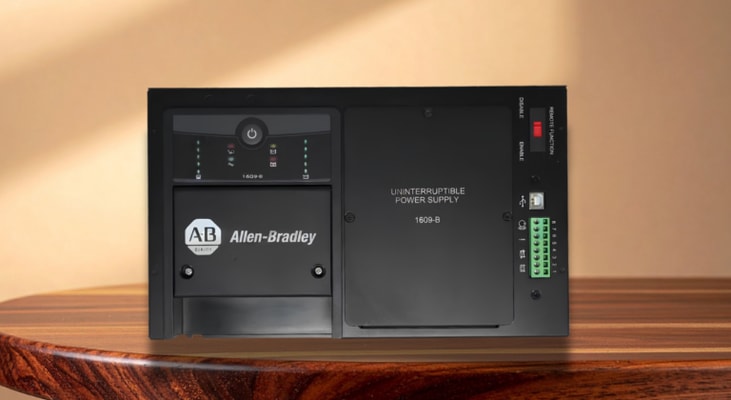
Modern industrial automation relies heavily on Programmable Logic Controllers (PLCs). PLCs are ruggedized, microprocessor-based industrial computers used to govern critical industrial processes across chemical processing plants, oil & gas systems, food packaging systems, water & wastewater treatment plants, manufacturing, and other industrial complexes. While control engineers and system integrators invest substantial effort into optimizing PLC control code, network configurations, and field input/output devices, a stable PLC power supply is equally vital for reliable system performance. Although PLCs are inherently designed to withstand harsh environmental conditions, such as vibration, extreme temperatures, and dirt, they do require a highly consistent power supply to function properly. An uninterrupted power supply prevents data corruption, logic errors, and catastrophic downtime in any PLC-controlled automation system. A stable PLC power supply readily converts variable line...
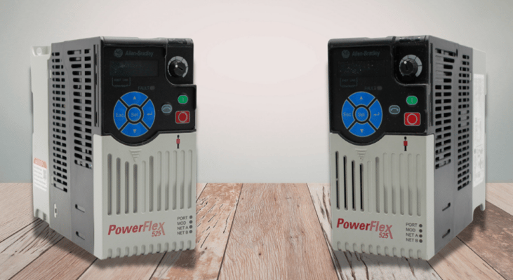
When it comes to installing motor drives, there are three different ways to do it: Exactly by the book to ensure maximum efficiency, the “yeah, that looks about right” way, and the wrong way. The by-the-book way will go exactly as you would expect. It’s the “about right” way that may lead to unforeseen struggles, such as a hot motor, when the smaller details are overlooked. Believe us, there is no shame in these installs, and if you’re wondering why your motors are getting hot after a VFD install, stick around to find out why. Heat is the leading cause of industrial motor failure. The 10-Degree Rule is a good baseline to calculate motor insulation degradation based on how hot the motor is running relative to its rated temperature: \-20C leads to 4x longer life -10C leads to 2x longer life +10C leads to 2x shorter life +20C leads to 4x shorter life Order Allen-Bradley PowerFlex 525 Drives Here Your motor will have an insulation class rating that indicates the maximum temperature to...
Modern-day electronics have become the new normal within industrial settings. Take a look up in a factory, and you may see rows of LED lights. Turn to the right, and a conveyor line powered by VFD-driven motors could be humming along, while to the left, a robotic arm may be sorting products for palletization. It’s incredibly easy to see this technology on the surface: you plug it in, set the parameters, and watch it go. The problem is that all of this equipment has to live on the same electrical system. Just as drinking dirty water would harm our bodies, electronics receiving dirty power could also show symptoms of their own illness, such as increased heating, lower life spans, and nuisance tripping. Harmonics are among the most common forms of dirty power and are produced by devices such as rectifiers, inverters, fast-switching devices, and more. These are your VFDs, variable power supplies, switch-mode power supplies, PWM-operated devices, and even EV chargers. Before getting into...
Variable Frequency Drives (VFDs) are widely used in modern industries to optimize process control, minimize power consumption, and extend equipment lifespan. The Allen-Bradley PowerFlex series stands out for providing high-performance motor control with precise torque control and simplified automation integration. However, VFD operations can induce damaging high-frequency stray currents and common-mode voltages on motor shafts. These high-frequency currents often discharge through the motor bearings, resulting in accelerated bearing wear and premature equipment failure. The destructive impact of VFD-induced high-frequency currents on motor bearings is a widely recognized engineering issue. Connecting standard AC motors to variable frequency drives (VFDs) like the PowerFlex drives exposes them to stray currents and high-frequency voltage spikes. When under pure sinusoidal utility power, destructive stray currents do not exist. Catastrophic mechanical failure and structural degradation...
Mechanical wear in motor-driven systems is inevitable. It usually stems from repeated stress events, such as hard, abrupt stops, frequent cycling, or sudden load changes. These events can be reduced with motor control to minimize wear and tear on your system. This is where AC drives, or variable frequency drives (VFDs), come into play. They are installed for superior motor control, allowing the user to adjust voltage, frequency, torque, and speed to allow for a more efficient system. Learning how to properly do so will pay dividends in a smoother-running system. Direct-on-line (DOL) motor starts are the primary initiator of premature mechanical wear in industrial systems. When a three-phase induction motor is energized without drive control, inrush current reaches 600–800% of full-load rated current within the first 100–200 milliseconds. The resulting electromagnetic torque spike can reach 150–300% of rated torque and is transmitted instantaneously through the shaft, coupling, and...
Allen-Bradley PanelView terminals from Rockwell Automation are core Human-Machine Interface (HMI) solutions for industrial automation. While ideal for climate-controlled industrial settings, cold storage and outdoor deployments present significant extreme environmental challenges, such as sub-zero temperatures and direct UV & solar radiation. Optimizing PanelView terminals for such extreme environmental conditions requires strategic hardware selection (e.g., robust enclosures such as NEMA 4X-rated enclosures), precise thermal management strategies, and comprehensive preventive maintenance practices. This article explores the operational parameters of PanelView terminals deployed in extreme industrial environments. It presents a comparative analysis of specific PanelView terminal models, practical environmental mitigation strategies, and proactive failure-prevention techniques. Standard PanelView terminals are designed to operate within specific temperature ranges (typically 0°C to...
Variable Frequency Drives (VFDs), servo drives, and DC drives are the workhorses of motion control in industrial automation. Their internal semiconductor junctions, IGBTs, power diodes, and electrolytic capacitors, are thermally sensitive. Empirical data from semiconductor reliability models (Arrhenius equation) indicate that a 10°C rise in junction temperature reduces component life by approximately 50%. Conversely, proper thermal management can extend drive life beyond the manufacturer’s 10-year design horizon. This article provides a quantitative framework for cooling and enclosure design specific to drives, focusing on heat load calculation, airflow dynamics, ingress protection (IP) trade-offs, and active versus passive cooling strategies. For engineers responsible for specifying, installing, or maintaining drives, understanding these principles is not optional, it is the difference between a 5-year service life and a 15-year one. To extend drive life, one must first understand...