Reducing Mechanical Wear with AC Drive Control
Mechanical wear in motor-driven systems is inevitable. It usually stems from repeated stress events, such as hard, abrupt stops, frequent cycling, or sudden load changes. These events can be reduced with motor control to minimize wear and tear on your system.
This is where AC drives, or variable frequency drives (VFDs), come into play. They are installed for superior motor control, allowing the user to adjust voltage, frequency, torque, and speed to allow for a more efficient system. Learning how to properly do so will pay dividends in a smoother-running system.
Root Cause: Mechanical Stress from Uncontrolled Motor Starts
Direct-on-line (DOL) motor starts are the primary initiator of premature mechanical wear in industrial systems. When a three-phase induction motor is energized without drive control, inrush current reaches 600–800% of full-load rated current within the first 100–200 milliseconds. The resulting electromagnetic torque spike can reach 150–300% of rated torque and is transmitted instantaneously through the shaft, coupling, and driven equipment as a torsional impulse.
Traditional methods of controlling motor speed, such as throttling valves or mechanical gears, impose significant mechanical stress on equipment. In contrast, AC drives provide a smoother, more efficient means of speed control that minimizes wear and tear on mechanical components and reduces the likelihood of breakdowns. Specific failure modes triggered by DOL starting include:
- Fretting corrosion on bearing raceways
- Gear tooth pitting from contact stress transients
- Elastomeric fatigue in flexible jaw couplings
- Keyway fretting on motor and driven machine shafts
Programmable Ramp Control: The Primary Wear Reduction Mechanism
The most directly impactful AC drive parameter for mechanical protection is the acceleration and deceleration ramp time. Acceleration and deceleration ramp times dictate how quickly the motor starts and stops, which is crucial for preventing mechanical shock. Modern drives offer programmable protections, such as acceleration/deceleration ramps, to help reduce mechanical stress during across-the-line starts.
During a controlled ramp, the drive increments output frequency in small steps, typically 0.01–0.1 Hz per control cycle, while scaling output voltage to maintain the programmed V/Hz ratio. Torque applied to the drivetrain at any instant is limited to what is required for the commanded rate of acceleration, not the electromagnetic maximum the motor can develop. Extending an acceleration ramp from the equivalent two-second DOL transient to a 10–15-second controlled ramp in a conveyor application reduces peak shaft torque proportionally over that interval. On deceleration, the drive controls the rate at which kinetic energy is extracted from the rotating load via the DC bus braking circuit, preventing the torsional reversals that occur when inertia-heavy loads are stopped by mechanical means alone.
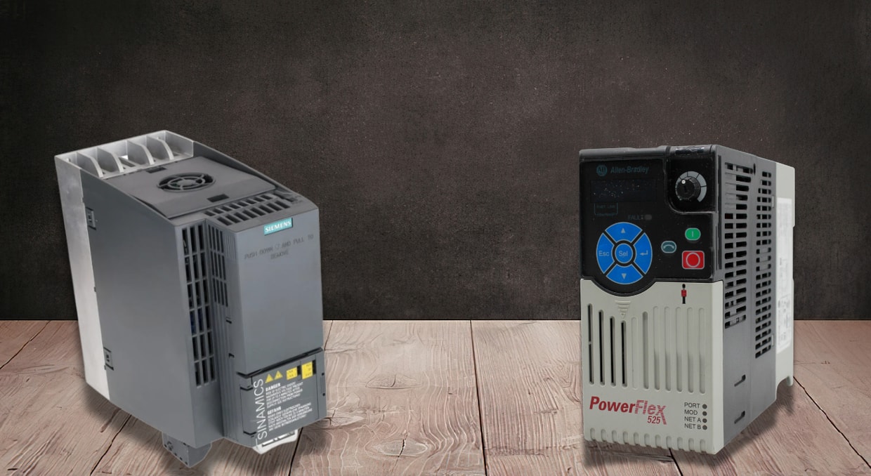
S-curve ramp profiles, available on platforms including Allen-Bradley PowerFlex 525/755, Siemens SINAMICS G120, and ABB ACS880, add a sinusoidal transition at the beginning and end of each ramp phase, eliminating the jerk event that occurs even with linear profiling. This is particularly critical for conveyor and overhead crane applications, where mechanical shock at ramp transition points causes load-settling impulses in the structure.
V/Hz Scalar Control and Continuous-Speed Operation
The foundational control mode in general-purpose AC drives is scalar V/Hz control. At any given frequency, the VFD adjusts the output voltage proportionally to keep the flux in the motor’s magnetic circuit roughly constant. For example, a 460 V/60 Hz motor running at half speed (30 Hz) causes the drive to output approximately 230 V to maintain magnetizing flux and rated torque capability.
V/Hz control reduces mechanical wear primarily by enabling continuous variable-speed operation, eliminating the repetitive stop-start cycling that industrial processes would otherwise require to maintain process setpoints. A pump, for example, running continuously at 38–42 Hz to maintain line pressure imposes zero starting transients on the bearings and seals throughout that operating regime. The limitation of V/Hz in this context is that it does not independently regulate torque. Under changing loads, motor slip can shift along with the torque output. In equipment such as agitators, crushers, and paper winders, quick load changes can still create mechanical stress, especially when the system requires tighter control than basic open-loop operation can provide.
Sensorless Vector Control: Independent Torque and Flux Regulation
For applications where load torque varies significantly and continuously, sensorless vector control, also termed open-loop field-oriented control (FOC), provides substantially better mechanical protection. Sensorless vector VFDs can achieve approximately 1–2% speed accuracy and deliver 150–200% torque at low speeds, which is ideal for cranes and extruders operating under variable loads.
In sensorless vector mode, the drive’s DSP runs a continuous motor model that estimates the rotor flux angle and speed from the measured stator current and voltage. Stator current is decomposed into two orthogonal components: the magnetizing component Id and the torque-producing component Iq. By independently regulating both in real time, the drive maintains constant flux while modulating the torque output exactly to the load’s demands. Vector control systems are specifically designed to minimize stress on the motor, reducing mechanical wear and extending the lifespan of the motor and associated equipment.
The practical drivetrain benefit is torque clamping under transient load changes. If a conveyor belt encounters sudden material loading or a pump experiences a step increase in system resistance, the drive prevents the motor from producing uncontrolled breakaway torque. A configurable motor torque limit bounds the torque current component Iq, typically set to 110–150% of rated torque, thereby preventing gear-tooth contact stress events and coupling-element fatigue associated with uncontrolled torque transients.
Direct Torque Control
At the highest tier of AC drive control sits Direct Torque Control (DTC), developed by ABB and implemented in the ACS880 and ACS580 series. DTC directly computes and controls motor torque and flux in real-time without a fixed switching frequency, yielding extremely fast torque response and precise control even without encoders. This dynamic performance is comparable to that of servo drives and is particularly useful for applications such as hoists, cranes, and high-speed machine tools.
DTC bypasses the intermediate frequency-reference-to-torque chain used in V/Hz and FOC. Its hysteresis comparators directly select inverter switch states based on the error between estimated and reference flux and torque values, producing torque responses in under 2 milliseconds. For mechanical wear reduction, this eliminates torque overshoot events that would otherwise transmit through the drivetrain as impulsive forces, the class of event responsible for sub-surface bearing raceway fatigue and, in gear motors, the micro-plastic deformation that initiates White Etch Area (WEA) bearing damage.
Skip Frequency Bands: Eliminating Resonance-Induced Fretting
Every drivetrain possesses torsional or structural natural frequencies. Because of this, operating continuously at a speed where drive output frequency coincides with a system resonant frequency produces cyclic vibration amplification that accelerates bearing fretting, loosens interference fits, and fatigues shaft shoulders and keyways at a rate far exceeding normal design calculations.
Modern drives allow programming “skip frequency” bands to avoid running continuously at a speed that causes machine resonance. Torque ripple with modern PWM drives is already lower than with older six-step inverters, so such issues are less common, but the parameter remains essential for eliminating resonance. On Allen-Bradley PowerFlex drives, this is configured via parameters Skip Freq 1/2/3 and Skip Freq Band, defining a center frequency and bandwidth, for example, 23 Hz ±1.5 Hz, through which the drive passes without dwelling. On Siemens SINAMICS G120, parameters P1091 and P1101 serve the equivalent function. Eliminating dwell at resonant speeds prevents the cyclic bearing load variation that initiates fretting corrosion in press fits and bearing-housing bores.
Closed-Loop PID Control: Preventing Over-Cycle Wear
Closed-loop feedback systems compare actual motor speed with the desired setpoint and make continuous corrections, adjusting the inverter’s frequency and voltage to maintain the target without deviation. Beyond speed accuracy, closed-loop PID control in an AC drive eliminates the over-cycle events that accumulate mechanical fatigue.
With closed-loop control, the drive can respond more smoothly. Instead of slamming between running and stopping, it can slow down, speed up, or make smaller adjustments as the process changes. Modern AC drives often include built-in PID control for pressure, temperature, and flow applications, along with multiple speed references through digital inputs or networked control. The main benefits are improved speed accuracy, smoother operation, fewer harsh corrections, and less wear on the equipment doing the actual work.
Torque Limit Parameters and Electronic Drivetrain Protection
Most industrial-grade AC drives expose independent torque-limit registers for the motoring and regenerative operation quadrants. On the Allen-Bradley PowerFlex 755, parameters 596 (Torque Limit 1) and 597 (Torque Limit 2) allow separate limiting for forward and reverse motoring and for forward and reverse regeneration, each expressed as a percentage of the motor’s rated torque. Setting the motoring torque limit to 120% rather than the default 200% ensures the drivetrain is never loaded more than 20% above rated torque, regardless of how abruptly the process load changes.
This is electronically equivalent to installing a mechanical torque-limiting coupling, but without the compliance and backlash that mechanical overload clutches introduce. The drive’s response time, under 10 ms in vector-controlled modes, is faster than any mechanical slip coupling, meaning the torque event is arrested before significant mechanical impulse propagates into the gearbox or driven equipment.
Practical Configuration Guidelines for Wear Minimization
Translating drive capabilities into actual wear reduction requires deliberate parameter configuration rather than factory defaults. Acceleration and deceleration ramp times should be calculated from the load inertia (J, kg·m²) and the allowable peak torque, rather than estimated. S-curve ramp activation should be standard on all conveyor and material-handling applications. Torque limits should be set at 110–130% for variable-torque loads (pumps, fans) and 150% maximum for constant-torque loads (conveyors, compressors). Skip frequency bands should also be identified during commissioning by measuring vibration at the coupling and gearbox housing across the full speed range, and then programmed with ±1.5–2 Hz exclusion bands around each identified resonant frequency.
For applications where motor cable runs exceed 50–100 meters, output dv/dt or sine-wave filters must be installed to eliminate voltage-reflection transients that stress motor-winding insulation, a separate but equally important wear mechanism affecting winding-turn insulation life.
Final Thoughts
At the end of the day, an AC drive helps reduce mechanical wear by making the motor behave with more restraint. Instead of hammering the system with hard starts, abrupt stops, constant cycling, or sudden torque changes, the drive gives the motor a smoother way to respond to the load ahead.
That shows up in a few different ways. Ramp settings ease the motor into motion instead of shocking the drivetrain. Variable-speed operation lets pumps, fans, conveyors, and other equipment run closer to the process’s actual needs. Torque control helps prevent sudden mechanical abuse from changing loads, while skip frequency settings can keep the system away from speeds that cause vibration or resonance. Add in feedback-based control, and the drive can make smaller corrections instead of letting the machine bounce between too much and not enough.
None of this makes bearings, gearboxes, couplings, or seals last forever. Mechanical parts still wear out, and a bad setup can beat up a machine in a hurry. But when an AC drive is selected and tuned correctly, it gives the equipment a much better chance at reaching its expected service life. If you are also looking at servo drives for your application, we have an article here that goes over where AC and servo drives fit best.
Hard starts, torque shock, and poor speed control can take a real toll on motors, gearboxes, belts, pumps, and bearings. If your facility relies on AC drives to keep equipment moving, we at DO Supply can help you stay ahead of failures with replacement VFDs, Allen-Bradley PowerFlex drives, and repair options for aging or damaged units. Reach out today to keep your drive systems supported before mechanical wear turns into unplanned downtime.
DO Supply Inc. makes no representations as to the completeness, validity, correctness, suitability, or accuracy of any information on this website and will not be liable for any delays, omissions, or errors in this information or any losses, injuries, or damages arising from its display or use. All the information on this website is provided on an "as-is" basis. It is the reader's responsibility to verify their own facts.