RX3i CPU Selection Guide
A) CPE400
The RX3i CPU series has only one standalone CPU (IC695CPE400). It functions independently, unlike other models which are usually plugged into a backplane. Two mounting possibilities are facilitated; mount on a DIN rail or install in a cabinet. The CPE400 is the latest and most advanced CPU with unmatched processing power, performance, and features. It has a quad-core 1.2 GHz AMD G-Series processor. The operating system in this CPU is VxWorks, similar to all other CPU variants. This CPU operates in a temperature range from -40°C to 70°C, unlike all others having a 0°C to 60°C operating temperature range. CPE400 has battery-backed 64 Mbytes of RAM and a similar capacity non-volatile flash memory. CPE400 has built-in non-switched and four switched RJ45 Ethernet ports. Additionally, it has an Embedded Field Agent (EFA) RJ45 Ethernet connector, the specialty of CPE400 alone. In contrast, all other CPU models support high-speed PCI and Serial module backplanes for data transfer.
Switches
A user can access CPU settings through six push buttons available on the front side to perform various tasks. These include DISP, SEL, RUN, STOP, PHY PRES, and PWR.
OLED Display
The monochrome OLED display shows menus for operating systems. Its dimensions are 34.5 cm by 23 cm with 128 vertical and 64 horizontal dots. It is controlled by the DISP button, which moves it from menu to menu, and the SEL button, which triggers the current menu item to perform further actions. OLED display allows users to visit many settings, including Ethernet settings for LAN, set or view PLC modes, configure the sweep time, enable and disable the Inputs and outputs, display EFA settings, Issue Field Agent Command and check the status of Field Agents, and more.
Status Indicator LEDs
Various LED indicators are available, which depict several conditions and statuses regarding CPU scan, PLC states, temperature conditions, hard disk activity, faults, communication connections, and redundant units.
Micro-SD Card Slot
The memory card slot that supports a Micro SD card is positioned on the right side of the device at the same level as the OLED display. It works with all portable data storage device features. This interface works with SD, SDHC, and SDXC mSD-Cards for versions 3.0 and below. A cover is provided with a screw. It is recommended to ensure that the cover is in place throughout normal use to keep the CPE400 safe from electrical interference.
USB 3.0 interface
This CPU model has two USB ports that have normal USB Type-A connectors and are positioned beneath the faceplate of the OLED display. A 1.5 A fuse secures these ports. Maintaining the maximum power at 0.9 A for each connector is recommended when using them in normal operation. The USB senses occurrences of overcurrent and ceases normal operation once the conditions are met. The root cause needs to be identified in order to resume. The maximum cable length that can be used for port 1 and port 2 is 3.0 m and 15 cm, respectively.
Ethernet Ports
CPE400 is able to support four Ethernet LANs. For better efficiency of the CPE400 system, a separate microprocessor core is allotted for LAN1, LAN2, and LAN3. This superior quality of service is essential for a greater rate of communication. Front-panel Ethernet ports can connect to programming software via the Service Request Transport Protocol. The LAN2 port has been set to play the role of an embedded controller for PROFINET. LAN2, as well as LAN3, both have two RJ45 connectors. This means that networks with devices connected but have different data transfer speeds should be connected to their appropriate port. CAT5 (or even higher quality) cables are required to operate the LANs properly. The fourth network port is used as an EFA and is located on the lower part of the device. It can not be used as the standard Ethernet port. The Ethernet interfaces can determine the amount of information transmitted, along with the connection’s communication mode and the cabling configuration.
Field Agent
The CPE400 Embedded Field Agent can collect data locally before securely transferring it to the Predix Cloud via the EFA port. The PACSystems RX3i PLC retains control of the CPE 400’s remaining Ethernet ports as well as its serial port. The RX3i PLC can alter data collected from these ports and tag it for use in a control application.
Users accessing remotely, with a satisfactory security profile, can access cloud data from multiple sources, aggregate, and make decisions. For example, the CPE400 might be installed in a wind turbine control, but a remote user can monitor one hundred turbines; an organized, informative dashboard-style application will help identify which turbines need to be taken offline for maintenance.
Serial Port
The CPE400 CPU has a serial port with an RJ45 connector. It is labeled as COM and positioned on the device’s bottom. Software communication is not supported via this serial port. For the PME link, an Ethernet port is recommended. Moreover, Modbus is supported on the CPE400’s serial ports.
Display Port
A display port is provided at the base side of the CPU, which can be used to attach an external monitor or video adapter card. The port is marked as a DP++ video port.
Energy Pack Connector
The use of the Energy Pack in CPE400 is optional. A compatible Energy Pack is offered with a custom cable that fits into the connector. With the Pack installed, the CPU PLC function can continue normal operation from the power-failure condition.
Backward Compatibility
The CPE400 CPU is targeted as a PLC in the Rx3i PACSystems rack-less series. The existing project that utilizes another PLC can be converted utilizing PME’s Family Conversion function. In case of a dying or malfunctioning real-time clock (RTC) battery, the CPU keeps working properly, and the error only comes in the clock information. Battery replacement is recommended every five years.
B) CPE330
CPE330 is built on a dual-core 1.1 GHz AMD G-Series processor. CPE330 has battery-backed 64 Mbytes of RAM and a similar capacity non-volatile flash memory. CPE330 has a built-in non-switched and two switched RJ45 Ethernet ports. These Ethernet ports are 10/100/1000, similar to CPE400.
Serial Ports
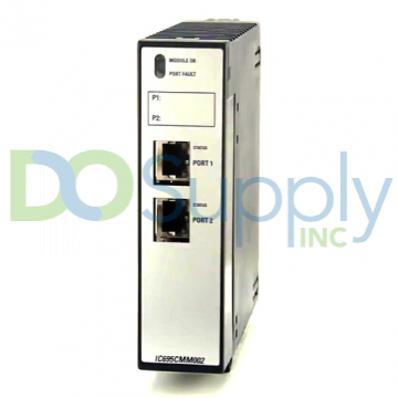
The serial port is not available on this CPU type. The built-in Ethernet ports are used to communicate with the CPU. To communicate serially, use IC695CMM002 and IC695CMM004 modules.
Ethernet Ports
CPE330 supports two distinct 10/100/1000 Ethernet LANs. The LAN1 connector is connected via the RJ45 located at the top and LAN2 connects with the lower two RJ45 connectors. The LAN1 connector does not have a switch, while the LAN2 connectors switch internally. Each of these embedded Ethernet interfaces will automatically detect the data’s speed along with the connecting link’s communication type and cabling configuration. Each of the embedded Ethernet ports requires a cable for communicating with the PME for programming and configuration.
1. Ethernet Network Configuration
Overlapping subnets result in intermittent Ethernet communications or a complete disconnection. Care is needed during the configuration stage to avoid overlapping IP addresses and subnet masks to each LAN in the network infrastructure. A condition called LAN collisions can happen between two devices with identical IP addresses.
2. Ethernet Gateway Operation
The CPE330 supports Ethernet gateway configuration on both LAN1 and LAN2. Each gateway has two LAN interfaces, each with its IP address. On each interface, only one gateway can be configured at a time. As long as LAN1 is operational, the LAN1 gateway takes precedence over the LAN2 gateway.
Switches
Three switches are placed behind the safety door: RUN, STOP, and RDSD. The RDSD UPLD button uploads the data or user program to RDSD from the CPU, whereas the RDSD DNLD button downloads the data from RDSD to the CPU. Additionally, a reset pushbutton is present above these switches, which will have a function added in the future.
Indicators
CPE330 is equipped with LED indicators vital for visualizing the functions and performance parameters of the CPU. A single LED indicator comprises multiple blinking fashions like ON, OFF, blink, changing colors, and unison animation style representing different conditions.
Ethernet Indicators
There are two LED indicators for Ethernet ports, one is named LINK, which is located up and the other is named 1 Gbps, located lower in position. These represent link connection, traffic detection, disconnection and data rate speeds through different lightning patterns.
Real-Time Clock Battery
The CPE330 is shipped with an RTC battery installed. There is no isolation barrier between the battery and the circuit. The RTC battery has no status indicators, but it is recommended to replace it every 5 years. The replacement battery must be IC690ACC001 from GE Automation & Controls.
Backward Compatibility of CPE330
The CPE330 can be replaced with a CPU320/CRU320 without upgrading the PME software. The configuration equality and the logic are preserved in PME for storing a project in CPE330, CPU320, or CRU320. Migrating CPU315 apps to CPE330 is possible by following the advised PME settings for saving the project in the relevant CPU version. Ethernet attributes cannot be altered. The CPE330 lacks serial ports. Any serial port operations related to the CPU320/CRU320 application must be transferred to a rack-based appropriate module (IC695CMM002 or IC695CMM004).
It is significant to note that only CRU320 projects can be saved to CPE330. Also, a CPE330 running in CRU320 compatibility mode can only store CRU320 projects. The CPU330 is typically referred to as the CPU320.
C) CPE305 and CPE310
These CPUs are built with 1.1 GHz Intel Atom processors. CPE305 has battery-backed 5 Mbytes of RAM and a similar capacity non-volatile flash memory, whereas CPE310 has 10 Mbytes of these memory types.
Serial Ports
The serial ports in these CPU models communicate with the external devices through serial interfaces. The CPE305 has a single RS-232 port, whereas the CPE310 has each RS-232 and RS-485 port marked as COM1 and COM2, respectively. The RS-232 connection does not provide the 5 Vdc power that other RX3i and 90-30 series CPUs provide.
Ethernet Port
The implanted Ethernet interface connects through a single RJ45 connector that detects the data rate of the connected link and detects communication mode and cabling layout automatically. The embedded Ethernet interface communicates with the PME programming and configuration software using the proprietary SRTP protocol. The CPE305/CPE310 CPUs provide two SRTP-server connections.
Switches
There is one pushbutton switch associated with RDSD to execute the data transfer process. Another three-state switch is present for uploading, downloading, and disabling the data transfer between RDSD and the CPU.
Indicators
Various CPU LED indicators are provided in theCPE305 and CPE310 for representing CPU state, data transfer processing, and fault conditions indications. CPE310 has two RDSD-related indicators, while CPE305 has only one. Ethernet indicators are also present in both CPU models which denote the communication link formation, data transfer rate, and traffic detection.
Real-Time Clock Battery
It is important to remember that the CPE305 and CPE310 both have an RTC battery and there are no diagnostics or indicators to check functional errors and the remaining life of the RTC batteries. The lifespan of the RTC battery is predicted to be 5 years. In a preventive maintenance plan, batteries must be replaced every five years. When the RTC battery is broken, the CPU’s time and date are reset at startup. Even if the RTC battery is broken or absent, the CPU will continue to function normally.
Backward Compatibility of CPE305 and CPE310
- The CPE310 can be replaced with a CPU310, but no change is required in the programming software.
- The CPE310 can be used to support CPU310 projects. The CPE310 can be set up as a CPU310.
- By enabling the RDSD port and storing CPU310 configuration in CPE310, CPU310 projects can be directly transferred to CPE310 models.
- A CPE310, which is set up as CPU310, records the faults related to the embedded Ethernet module, unconfigured module, and failed or damaged battery.
D) CPU315 and CPU320/CRU320
CPU315 is built with a 1 GHz Intel Celeron processor with 20 Mbytes of RAM and non-volatile flash memory each. The model is marked as mature and an alternative model of CPE310 or CPE330 is assigned for replacement. The CPU320/CRU320 utilizes a 1 GHz Intel Celeron processor with 64 Mbytes of RAM and 64 Mbytes of non-volatile flash memory. The model is also marked as mature and a suggested replacement is given as CPE330.
Serial Ports
Each of these CPUs offers two separate serial ports on board, which are accessible via connectors on both sides of the machine. Both COM1 and COM2 provide serial interfaces to external devices.
Indicators
Eight LEDs for CPUs indicate various CPU conditions. Two Comm LEDs indicate activity on both COM1 and COM2.
Error Checking and Correction
The RX3i series has the advantage that it offers several unique features above its predecessor series. One of the great features is redundancy processors. These processors have the task of error correction and checking (ECC). This processing takes some extra time and may sometimes slow down performance as the additional 8 bits are activated for the task.
E) CPU310
CPU310 is based on a 300 MHz Intel processor with 10 Mbytes of RAM and flash memory. The model was discontinued officially, and the recommended model for its replacement is CPE310. The details of the serial port available onboard in this CPU model are similar to that of CPU315. Also, Eight LEDs for CPUs provide various indications and information about the states and processes of the CPU and attached peripherals. The LED indicators present similar features as offered in CPU315.
DO Supply Inc. makes no representations as to the completeness, validity, correctness, suitability, or accuracy of any information on this website and will not be liable for any delays, omissions, or errors in this information or any losses, injuries, or damages arising from its display or use. All the information on this website is provided on an "as-is" basis. It is the reader's responsibility to verify their own facts.