Designing PLC Systems for Harsh Environments
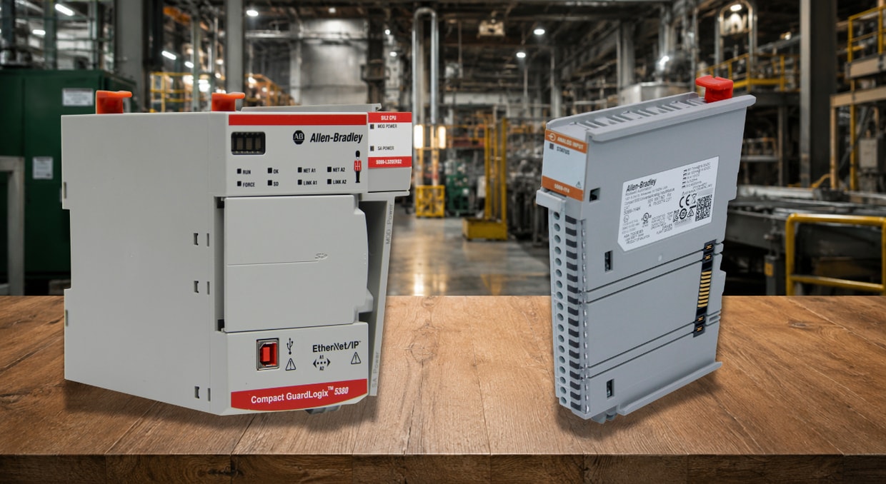
Although a PLC installed on a vibrating conveyor frame in a steel mill and a PLC sitting in a climate-controlled control room can belong to the same product family, the technical choices made for each installation are very different. Compared to traditional factory automation, industrial control systems utilized in hazardous or toxic industrial environments need to have far more robust designs and better environmental ratings.
Corrosive vapors, conductive dust, explosive gases, excessive humidity, loud electrical noise, and extremely high or low temperatures can all be found in these settings. Buying a more costly processor is not the only option when designing a PLC system for these circumstances. Conformal coating, vibration mounting, thermal management, enclosure selection, EMI shielding, and hazardous area classification are all systems engineering tasks that must be completed at different stages of the design process.
Defining the Environmental Stressors Before Selecting Hardware
Understanding the particular environmental stresses the PLC system will encounter is the first step toward designing for such a hostile setting. It is necessary to establish the stressor profile statistically rather than qualitatively before choosing any PLC type or enclosure grade. “Hot and dusty” is not a complete design requirement. A useful environmental profile would identify the expected temperature range, dust composition and loading, humidity, vibration spectrum, washdown exposure, corrosive contaminants, and nearby electrical-noise sources.
The documentation should establish:
- Minimum and maximum ambient temperature, including any daily or seasonal swing
- Particulate type, conductive (metal, carbon) versus non-conductive (cement, grain), since conductive dust changes the enclosure rating requirement
- Vibration profile in g-force and frequency, ideally measured rather than estimated
- Presence of corrosive vapors, chemical splash, or washdown requirements
- Classification of any explosive gas or combustible dust hazard zones present
- Electrical noise sources nearby, VFDs, welding equipment, RF transmitters
Every decision made later in the design is based on this stressor profile. In tough installations, the most frequent reason for premature PLC failure is skipping this stage and choosing hardware based on catalog familiarity.
Enclosure Rating Selection: IP and NEMA Classification
To stop dust or water from entering, a sealed enclosure is utilized. IEC 60529 is the standard that lists the various types and levels of protection an enclosure provides for its electrical equipment. The initial physical barrier between the PLC and its surroundings is the enclosure rating, which must be chosen appropriately by matching the IP or NEMA number to the real stressor profile rather than using a generic “industrial” grade.
Practical guidance for common harsh-environment categories:
- General dusty/dry industrial: IP54/NEMA 12 minimum, with conductive dust environments requiring sealed enclosures regardless of IP rating
- Washdown food and beverage: IP66 or IP69K, as required by the applicable equipment standard and washdown procedure.
- Outdoor or marine: IP66/NEMA 4X with corrosion-resistant materials and condensation management (breather/drain vents or enclosure heaters)
- Mining and underground: IP65 minimum with reinforced mechanical protection against impact, since underground environments combine dust, vibration, and physical strike risk simultaneously
PLC families used in mining must still be installed within enclosures and systems suited to the site’s dust, moisture, vibration, impact, and hazardous-location requirements. Suitability should be confirmed from the exact controller, I/O, enclosure, and certification documentation rather than inferred from the PLC family name.
Thermal Management Inside Sealed Enclosures
Heat produced by the PLC processor, I/O modules, and power supply can only escape through the walls of a sealed enclosure that keeps out moisture and dust. This leads to a direct conflict between thermal dissipation and dust/moisture protection, which needs to be addressed through intentional thermal design rather than relying solely on the enclosure rating.
Choosing PLC hardware with wide operating temperature ratings instead of relying solely on enclosure cooling, specifying enclosure-mounted heat exchangers or vortex coolers for high-ambient applications, and sizing the enclosure with an adequate internal air volume relative to dissipated power are all effective strategies. Certain ControlLogix-XT components are rated for operation from −25°C to 70°C. Some Micro800 controllers also provide extended temperature capability, although their limits are generally narrower; for example, many Micro820, Micro850, and Micro870 controllers are rated from −20°C to 65°C. The lowest-rated component in the assembled system establishes the usable temperature range.
A fan or cooler is another mechanical component vulnerable to dust intrusion and vibration fatigue; therefore, specifying this extended-temperature hardware class lessens reliance on active cooling, which is a failure point in severe conditions.
Vibration and Mechanical Shock Resistance
Conveyor structures, mobile machinery, mining equipment, and any installation near spinning machinery expose the PLC to intermittent shock loading and continuous mechanical vibration. Secure cable management, shock-absorbing materials, and sturdy PCB mounting all contribute to robustness to shock and vibration.
At the system design level, this translates into specific mounting and hardware decisions:
- DIN rail mounting with positive mechanical latching rather than friction-fit clips, which loosen under sustained vibration
- Vibration-rated PLC hardware certified to ANSI/ISA-S71.04 vibration classifications, where applicable
- XT-series PLC versions meeting specific safety requirements such as ANSI/ISA-S71.04-1985 Class GX, G3, G2, or G1, enabling them to withstand higher levels of mechanical vibration.
- Strain-relieved cable glands and cable management that prevent repetitive flexing at termination points
- Locking connectors (M12 threaded, rather than push-fit) on all field wiring interfaces exposed to vibration
Even when properly torqued initially, terminal block screws on vibrating equipment eventually come out. To address this failure mode, spring-clamp terminal technology, which maintains constant contact pressure independent of vibration, is increasingly specified over screw terminals in these applications.
Conformal Coating and PCB-Level Protection
Use conformal coatings (acrylic, silicone, urethane) or complete encapsulation with epoxy-silicone potting to shield PCB assemblies from moisture, salt spray, chemicals, and particles. Conformal coating on the PLC’s internal PCB assemblies offers a second, independent layer of protection against moisture and contaminants that eventually seep into even well-sealed enclosures over years of use due to cable gland seals, gasket degradation, and door seal wear. The enclosure serves as the first layer of environmental protection.
Conformal coatings provide improved resistance to dust, shock, vibration, chemicals, filth, abrasion, fungus, moisture, and mechanical stress. Even in situations where the enclosure rating alone would theoretically be adequate, choosing an XT-rated processor over a standard-rated equivalent for installations in coastal, high-humidity, or corrosive-vapor environments is justified because the “XT” PLC versions are typically conformally coated as standard by the manufacturer. Over the course of a multi-decade service life, the coating serves as insurance against the enclosure’s inevitable, slow deterioration.
EMI/RFI Shielding and Electrical Noise Immunity
Because electrical noise from motors, welding equipment, and high-power transmission lines permeates many industrial settings, electromagnetic compatibility is also crucial. Stable operation may be ensured through shielding and careful PCB design. Beyond the internal hardware of the PLC, the following engineering techniques are used at the system design level to reduce noise-induced faults:
- Physical separation of PLC signal wiring from AC power and VFD output cabling, maintained at a minimum of 300mm in parallel runs
- Shielded, twisted-pair cabling for all analog signal wiring, with shield grounded at one end only to prevent ground loop currents
- Ferrite chokes on cable entries into the enclosure at high-EMI sites such as near induction heating or welding equipment
- A single-point grounding scheme for the enclosure and all bonded metal components, avoiding multiple ground paths that create circulating currents
One criterion unites all protection techniques: components exposed to potentially hostile environments must not experience transients, excessive current, overvoltage flow, or undesirable temperatures. At the system level, power protection may include coordinated surge-protective devices, properly rated control transformers or power supplies, DC buffering or UPS equipment, branch-circuit protection, and isolation where required. Protection should be coordinated with the facility grounding system and applicable surge-protection standards.
Hazardous Area Classification and Intrinsic Safety
The PLC system design must account for hazardous area categorization under standards such as IEC 60079 or NFPA 70 (NEC Class/Division or Zone systems) in settings containing explosive gases or flammable dust. Fertilizer manufacturing sites, hydrogen processing facilities, chlorine-based water treatment systems, offshore oil and gas platforms, and combustible dust plants are typical examples.
For purge-and-pressurize enclosures (Types X, Y, or Z per NFPA 496) or intrinsically safe barriers used to interface with field devices that must remain inside the classified zone, the standard engineering approach is to locate the PLC processor and main I/O outside the classified hazardous area whenever possible. Where intrinsically safe field circuits are used, approved barriers, galvanic isolators, or intrinsically safe remote I/O may allow control equipment to remain in an unclassified area while connecting to properly assessed field devices in the classified area. The complete loop must comply with the applicable control drawing, entity parameters, gas or dust group, temperature class, wiring method, and local code requirements.
Power Supply Robustness and Redundancy
Voltage drops from massive motor starters, transients from switching operations, and generator-supplied power with intrinsic instability in frequency and voltage are widespread. Power quality in tough industrial situations is often lower than in regulated environments. To prevent early-stage failures at the onset of a power disturbance, voltage supervisor integrated circuits (ICs) are responsible for overvoltage and undervoltage protection. The power quality problems that are disproportionately common at remote or harsh-environment sites where utility power infrastructure is less robust than at a typical manufacturing facility can be prevented by specifying a PLC power supply with a wide input voltage tolerance band, dedicated transient suppression, and, for critical applications, redundant power supply modules with automatic failover.
Final Thoughts
In conclusion, environmental stress testing documentation, enclosure rating, thermal management, vibration mounting, conformal coating, EMI shielding, hazardous area classification, power robustness, field wiring practice, and lifecycle maintenance planning are all layers in the process of designing a PLC system for harsh environments. In essence, a PLC is a digital computer that has been ruggedized to handle industrial operations in challenging conditions, such as high temperatures and damp, dry, and dusty environments. However, this baseline robustness is predicated on proper system-level design. Even with certified hardware, a system fails when the correct CPU is specified, but enclosure, vibration mounting, and field wiring discipline are neglected. The dependability required for the harsh-environment application is achieved only by addressing all 10 aspects at once. For more information on harsh environments, we wrote an article covering the top PowerFlex drives for harsh environments here.
Designing a PLC system for harsh environments requires more than choosing a rugged enclosure. IP ratings, temperature limits, power quality, and more need to all work together to ensure they meet the proper requirements for your plant. If you need help selecting PLC hardware or replacement components, contact us at DO Supply! Our team can help you find the right equipment for your system, all backed by our two-year warranty. We carry everything from XT-rated PLCs to hardware accessories, motion control, and more.
DO Supply Inc. makes no representations as to the completeness, validity, correctness, suitability, or accuracy of any information on this website and will not be liable for any delays, omissions, or errors in this information or any losses, injuries, or damages arising from its display or use. All the information on this website is provided on an "as-is" basis. It is the reader's responsibility to verify their own facts.