A User’s Guide to PowerFlex DC Drives: Tips and Tricks
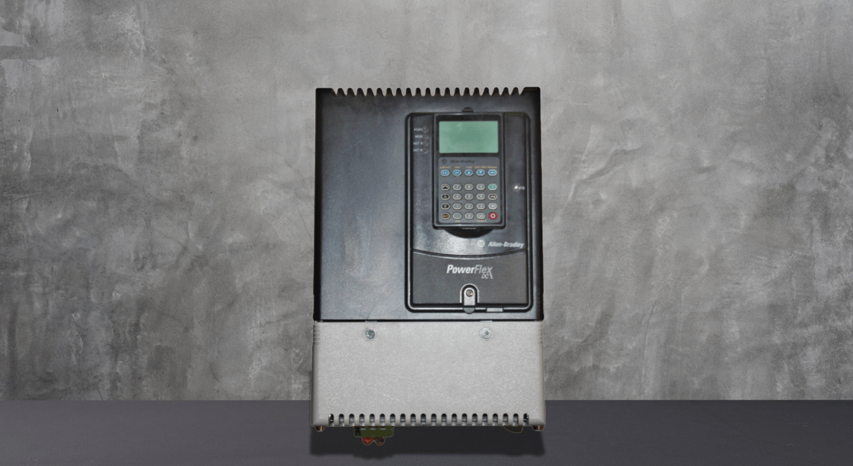
Navigating the installation, setup, and troubleshooting of PowerFlex DC drives can greatly enhance your automation system’s performance. This article provides practical tips and tricks for working with these drives, from installation and wiring essentials to power distribution, grounding, and circuit protection. It delves into parameter configurations, motor feedback tuning, fault monitoring, and troubleshooting, enabling users to optimize drive functionality. Users can quickly resolve issues, improve accuracy, and ensure consistent operation in various industrial applications by understanding specialized parameters and diagnostic tools. Below, we have discussed some tips and tricks for users to utilize the PowerFlex DC Drives.
Installation and Wiring Product Advisories
Ensure you adhere to installation rules and any product cautions while installing the PowerFlex DC Drives. Mount the drive firmly and keep the necessary clearances to promote heat dissipation and prevent electrical interference. Make sure that the working conditions—such as the minimum mounting clearances and the maximum ambient air temperature—meet the manufacturer’s requirements. Verify that the drive’s weight and dimensions fit the allotted area. For bigger drives, employ the right lifting procedures. For best results, set up isolation transformers and line reactors and remove drive covers as directed by the frame size (A, B, C, or D).
Power Distribution and Grounding Requirements
Ensure accurate grounding and power distribution for safety and effective drive operation. Connect the safety ground (PE) to prevent electrical faults and check the integrity of the power feeder connections, including grounds for encoder/resolver signals. Install grounding carefully, especially for ungrounded or high-impedance neutral systems, to minimize risk. Follow CE conformity and low voltage directive guidelines, adhering to EN 61800-3 and EMC Directive standards. Proper grounding minimizes electromagnetic interference (EMI) and ensures the drive functions correctly within its pollution degree rating.
Power Circuit Protection and Wiring
Protect the PowerFlex DC Drive with power circuit protection measures, ensuring control power and power wiring meet protection requirements. Confirm that AC input and DC output voltage specifications align with the setup. Connect to the armature and field converter precisely and establish proper connections for armature voltage feedback at the designated terminal. Use dynamic brake resistors where necessary to prevent overvoltage conditions, and configure DIP Switch S14 according to installation requirements for proper operation.
Control Circuit and I/O Signal Wiring
Ensure that the input power for the control circuit satisfies the necessary specifications to allow drive control. Frame sizes C and D require cooling for the heatsink fan to maintain appropriate temperature management. Accurately connect the armature fuse signal terminals, then set up DIP switches and jumpers for I/O functions. Effectively route I/O signals and control wiring, including connections for DC analog tachometers and digital encoders at the appropriate terminal blocks. Correct wiring is necessary for resolver feedback module installations to preserve feedback accuracy and avoid electrical noise.
Drive Start-Up Checklist
For a secure and seamless startup procedure, see the Drive Start-Up Protocol before starting the PowerFlex DC Drive. To guarantee effective performance and safety, confirm that all necessary configuration settings, power wiring, and control/I/O wiring are accurate. By following safety procedures and minimizing starting mistakes, this detailed checklist lowers the possibility of misconfiguration and other operational problems while enabling a more effective initialization process.
Applying Power to the Drive
Before providing electricity to the drive, verify that all control and power cabling comply with product standards. Turn on the control circuits and ensure that the control voltages are within acceptable ranges. The power supply can be methodically turned on to avoid overloading circuits and ensure the setup is ready for the following procedures.
Loading Default Settings and Parameter Configuration
Once control voltages have been confirmed, load default settings and set up commonly used parameters according to operating needs. For customized functionality, change parameters like torque limits, acceleration rates, and current restrictions. Ensuring these settings maximizes control over motor torque and speed and aligns the drive with particular motor performance requirements. Customized drive responses are provided by this crucial phase, which also sets the stage for further parameter tweaking to meet application requirements.
Motor Feedback and Speed Regulation Tuning
After that, check the feedback polarity for precise response, confirm motor rotation, and adjust the current regulator to guarantee motor stability. Adjust the speed regulator to achieve the required operating efficiency and adjust the speed feedback settings to match your system’s needs. Check the speed reference settings to maximize drive responsiveness and improve accuracy in speed control applications. These last tweaks guarantee precise and seamless motor control and enhance the drive’s performance.
Understanding Parameters and Organization
PowerFlex DC drive parameters are essential for setting up and personalizing drive operations. The File–Group–Parameter Order methodical arrangement of parameters makes it easy for users to find settings. By grouping options into numbered lists, this layout simplifies the configuration process and adds clarity. Depending on the application’s demands, switching between basic and advanced views is simple, which display varying degrees of control.
Navigating Parameter Views and Cross-Referencing
Both Basic and Advanced Parameter Views are available on PowerFlex DC drives, catering to different degrees of user proficiency. While advanced views provide more detailed modifications for optimal performance, basic views show the essential drive parameters, which are perfect for beginning deployments. Cross-reference tables by name and number also make it easier to quickly retrieve particular parameters, cutting down on setup time. This organized display increases workflow efficiency, making sure that all parameter changes are easily accessible.
File-Specific Parameters for Control and Monitoring
The PowerFlex DC arranges key operating controls drive into specific files called the Monitor File, Motor Control File, Speed Command File, and Dynamic Control File. Specialized settings for specific modifications are included in each file. These range from dynamically tweaking drive responses to monitoring motor conditions, controlling torque, and modifying speed control. Drive functions may be adjusted by users, giving them the freedom to meet particular control requirements and preserve peak performance under a range of load scenarios.
Specialized Files for Applications and I/O Communications
The Communications File and Input/Output (I/O) File control disk connectivity and interaction with external systems, while the Applications File and Utility File provide customized parameter configurations for particular applications. These files provide the complicated command structures needed in automation networks, as well as data sharing and system integration. By modifying these settings, users may improve control accuracy, optimize data flow, and increase the drive’s usefulness in linked applications while streamlining communication protocols.
Faults and Drive Status Monitoring
PowerFlex DC drives use drive status indicators and HIM (Human Interface Module) warnings to indicate a variety of system issues. Examining the Drive Status and HIM Indicators helps identify and track faults by offering insight into the system’s health. Through consistent monitoring of these indications, users can identify problems before they become serious. One essential tool is the HIM display, which notifies users of required actions and offers real-time feedback on drive operations.
Clearing Faults and Alarms Manually
Alarms and faults might need to be fixed right away. After a disruption, PowerFlex DC drives can restart operations by using Manual Fault Clearing. Comprehending particular fault descriptions guarantees that users may promptly detect problems ranging from communication errors to thermal overloads. Operational stability can be preserved by manually clearing alarms for non-critical problems. Alarm descriptions assist users in understanding the causes of alarms to fix system issues without requiring prolonged downtime.
Troubleshooting Common Drive Issues
Certain Corrective Actions can be used to address common PowerFlex drive problems, such as when the drive begins, but the motor fails to rotate or does not achieve the requested speed. Other problems, such as the motor rotating in the incorrect direction or suddenly reaching its maximum speed, have specific troubleshooting methods. By following these protocols, operators may effectively address typical drive issues, preserving steady drive performance and averting interruptions.
Testpoint Codes for Diagnostic Precision
For precise diagnostics, the drive offers Testpoint Codes and Functions that let users evaluate certain parts. By detecting signal problems, helping to modify drive operations, and verifying circuit integrity, these codes facilitate advanced troubleshooting. Frequent use of these test points during diagnostics improves system dependability by giving accurate input on the operation of the drive and motor. Test point analysis is essential for thorough drive evaluation and preventative maintenance procedures.
Final Thoughts
In conclusion, understanding the PowerFlex DC drives requires a methodical approach to installation, wiring, parameter configuration, and troubleshooting. By following essential tips on grounding, power distribution, circuit protection, and precise parameter adjustments, users can maximize drive performance and system reliability. Understanding file-specific parameters for control, specialized application files and diagnostic tools like HIM indicators and test point codes helps in pre-emptively identifying and resolving faults. This proactive strategy empowers users to maintain operational consistency, optimize drive functionality, and respond effectively to any issues that arise. Utilizing these insights ensures that PowerFlex DC drives operate at peak performance across varied industrial applications. Though if you are curious to read how the DC series compares to the AC, we have an article for that here.
We at DO Supply specialize in Allen Bradley drives like these and many more. We carry thousands of PowerFlex drives and accessories waiting to be delivered to your doorstep. Unsure of what to pick? No worries! Give us a call or shoot us an email, and our team of specialists can pair you with the perfect drive to take your automation solution to the next level.
DO Supply Inc. makes no representations as to the completeness, validity, correctness, suitability, or accuracy of any information on this website and will not be liable for any delays, omissions, or errors in this information or any losses, injuries, or damages arising from its display or use. All the information on this website is provided on an "as-is" basis. It is the reader's responsibility to verify their own facts.