Safety Considerations in DC Drive Systems
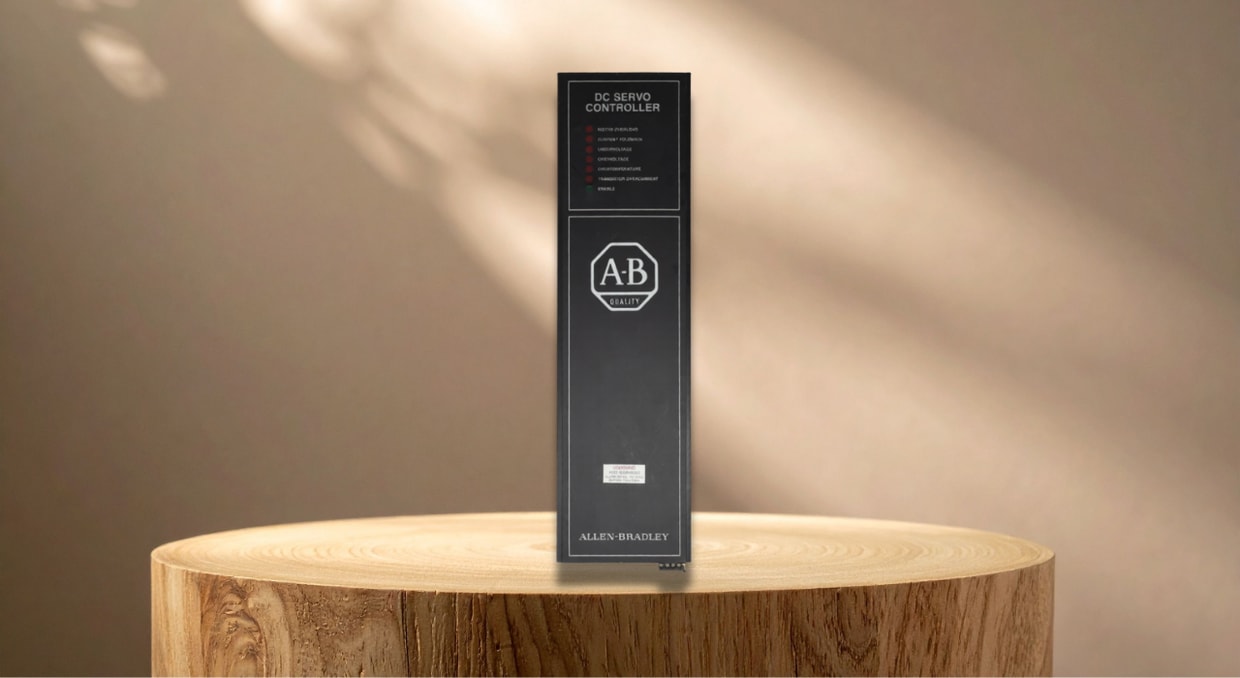
Safety is the foundation of hazard-free and reliable industrial applications. DC drives operate at hazardous current and voltage levels to regulate the field current and armature voltage, thereby precisely controlling motor speed, torque, and direction. Therefore, strict adherence to established electrical safety protocols such as proper grounding, isolation, and Lockout/Tagout (LOTO) procedures, as well as compliance with IEC 61800-5-1 standards, is essential in DC drive systems. It helps isolate dangerous voltages and minimize arc flash hazards, protecting both personnel and machinery from catastrophic electrical faults. This article provides a detailed technical analysis of the essential safety considerations for designing, operating, and maintaining DC drive systems.
What is a DC Drive System?
A DC drive system is an electronic motor controller designed to regulate the torque, speed, and rotational direction of a DC motor. It achieves this by actively modulating the current and voltage applied to the motor’s armature and field windings, often using advanced power electronics such as Pulse-Width Modulation (PWM) or SCR (Silicon Controlled Rectifier) phase-control. It interfaces between the power supply and the DC motor. These drives primarily consist of a power conversion unit and control circuit. The power conversion unit typically employs either a thyristor-based controlled rectifier (used for AC-to-DC conversion) or a Pulse-Width Modulation (PWM) chopper (utilized for DC-to-DC modulation).
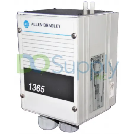
For over a century, DC motors and drives have remained a cornerstone of industrial control systems. While AC motors and Variable Frequency Drives/AC drives dominate most variable-speed and general industrial applications, DC drive systems remain a preferred solution in industrial processes that demand highly precise speed regulation, exceptionally low-speed torque/ high starting torque, and smooth regenerative braking. They are widely used in demanding, high-power industrial applications such as steel rolling mills, mining operations, paper machines, specialized crane hoists, and certain robotics. Because high electrical energy is involved in these DC drive systems, safety requirements are strict engineering standards mandated by international safety protocols and not mere recommendations.
Types of Electrical and Mechanical Hazards
A comprehensive understanding of the specific risks affecting DC drive systems is essential for developing a robust safety protocol. These hazards typically fall into four distinct categories: thermal (overheating, insulation breakdown), electrical (arc flash, shock), mechanical (component fatigue, vibration), and environmental (dust, moisture, corrosive gases).
Electrical Shock Hazards
The specific nature of DC power makes electrical shock a major hazard. Unlike Alternating Current (AC), which drops to zero volts twice per cycle and periodically reverses polarity, DC flows continuously in one direction without dropping to zero. This constant current flow makes electrical arcs incredibly difficult to extinguish. DC shocks are much more hazardous than AC shocks because the continuous, uninterrupted DC flow induces prolonged muscle contraction, making it physically impossible for personnel to let go of an energized conductor.
Major causes of DC electrical shocks include:
- High DC Bus Voltage: Despite disconnecting incoming AC power, lethal levels of residual voltage can be retained in the large internal capacitors of a DC drive system.
- Ground Faults: When insulation fails in a DC drive system, high-voltage wires can contact the motor casing, energizing the entire frame. Without proper equipment grounding, this poses an immediate risk of severe shock or electrocution to personnel who contact the frame.
DC Arc Flash Hazards
A DC arc flash is an explosive, high-temperature energy discharge that occurs when electric current escapes its designated circuit and travels through the ionized air between conductors or to the ground. With the widespread adoption of battery storage, EV infrastructure, large-scale DC systems, and solar energy, periodic assessment of DC arc hazards to ensure compliance with NFPA 70E and OSHA standards has become a major safety priority.
- Sustained Arcing: DC arcs tend to last longer and are not self-extinguishing because of the continuous nature of DC voltage. This results in incredibly severe burns and elevated energy levels.
- Equipment Enclosures: An internal arc flash inside an unventilated or cramped DC drive cabinet can trigger a “focusing effect.” This effect concentrates radiant energy and rapidly expands superheated gases, exponentially amplifying both thermal effects and explosive pressure on nearby personnel and the surrounding environment.
Thermal Hazards and Fire Risks
When a DC drive system is running, it dissipates heat due to power losses in its switching circuits (MOSFETs or IGBTs) and the internal operation of the connected DC motor. These power losses are due to:
- Overheating: Ignition and melting of the internal components are caused by elevated ambient temperatures, clogged filters, and blocked fans.
- Mechanical jamming forces the connected DC motor into a locked-rotor state, which eliminates the back-EMF. As the DC drive continuously injects current into the stationary motor armature, the electrical energy is converted into uncontrolled resistive heating. The concentrated thermal energy causes degradation of the winding insulation, risking thermal runaway or winding ignition.
Mechanical and Overspeed Hazards
DC motors connected to DC drive systems feature distinct torque-speed profiles — such as inverse speed regulation and high starting torque — that can trigger unique safety hazards, such as catastrophic mechanical failure or runaway conditions under no-load conditions.
- Runaway Condition: The magnetic field of a DC series motor is connected to the armature in a single path. In the event of a sudden disconnection of the magnetic load, the internal current drops sharply. This leads to a sharp increase in motor speed that physically destroys the motor due to intense centrifugal force.
- Unexpected Restarts: Shutting down DC drive systems because of faults and restarting without informing the operators poses a hidden danger. This is because unexpected movement of parts can cause crushing injuries and entanglement.
DC Drive Protection Measures
Compliance with International Safety Standards
Operators, system integrators, and manufacturers of DC drive systems are required to comply with a suite of international safety standards to mitigate the electrical and mechanical hazards discussed above. The standards include:
IEC 61800 Series
The IEC 61800 is a comprehensive series of international standards that defines the requirements for electrical power, safety, energy efficiency, and electromagnetic compatibility (EMC) for both AC and DC motor drive systems. It entails:
- IEC 61800-1: Specifically addresses general requirements for low-voltage variable-speed DC power drive systems and focuses on rating characteristics. This standard addresses the parameters required to ensure a safe interaction within the power grid and the motor.
- IEC 61800-5-1: This safety specification addresses thermal, electrical, and energy-related hazards. It provides a comprehensive outline of the requirements needed to ensure adequate insulation within accessible drive parts and in circuits capable of carrying a voltage above 50 DC, either AC or DC. This series also includes protective bonding and clearance distances.
- IEC 61800-5-2: Particularly addresses functional safety. This document provides the design of safety functions and how they should be implemented to avoid an unexpected startup.
- IEC 61800-5-2: Particularly addresses functional safety. This document provides the design of safety functions and how they should be implemented to avoid an unexpected startup.
UL Standards
- UL 61800-5-1: This standard is intrinsically harmonized with the IEC 61800-5-1 safety standard. It requires DC drives to satisfy stringent construction, testing, and performance benchmarks to ensure compliance with strict global safety requirements for thermal and electrical hazards.
Advanced Drive-Based Safety Functions
Contemporary DC drive systems incorporate built-in functional safety features to mitigate potential hazards. They utilize specific IEC 61800-5-2 subfunctions that disconnect drive power while keeping the main power supply active, thereby ensuring safety, minimizing downtime, and increasing productivity. The inbuilt safety functions include:
Safe Torque Off (STO)
The Safe Torque Off feature is the most widely deployed safety mechanism in DC drives. It is used to prevent unexpected motor start-ups.
- Mechanism: When the STO function is activated, the power supply to the DC motor that produces rotational torque is disconnected from the connected DC drive. This causes the motor to coast to a stop. The motor’s rate of deceleration depends entirely on the system’s frictional forces, natural inertia, and applied external loads.
- Safety Benefit: The STO feature ensures that there are no accidental motor restarts during operations in a hazardous area by preventing the motor from generating rotational force.
Safe Stop 1 (SS1) and Safe Stop 2 (SS2)
Safe Stop 2 (SS2) and Safe Stop 1 (SS1) are drive-based functional safety features that use the motor’s active braking torque to bring industrial machinery to a controlled standstill, rather than allowing the machine to coast to a halt.
- Safe Stop 1 (SS1): The DC drive uses a braking ramp to gradually decelerate the connected DC motor and afterward activates the STO function when the motor comes to a halt.
- Safe Stop 2 (SS2): It functions the same as SS1; it also uses a braking ramp to slow down the motor, but allows the motor to run even when in a standstill position.
Safely Limited Speed (SLS) and Safe Speed Monitoring (SSM)
In many industrial applications, operators often require access to machinery during active operation for maintenance tasks, continuous threading, or live inspections. However, performing active maintenance without shutting down the machine can create severe entanglement or crushing hazards; hence, the need for SLS and SSM safety features.
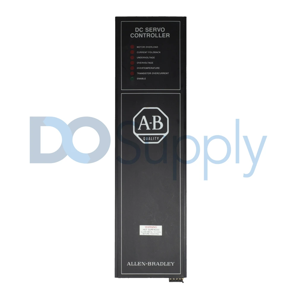
- Safely Limited Speed (SLS): This feature prevents the DC drive from exceeding a pre-defined safe threshold speed. To maintain the defined maximum speed, the DC drive monitors the kinematic quantities. In circumstances where this speed is exceeded, the drive system activates the SLS feature, which decelerates the drive to a safe speed. This allows operators to perform manual setup or maintenance tasks while the machine is running at a controlled, slow speed.
- Safe Speed Monitoring (SSM): This function ensures that safe operations are possible by sending an output signal that indicates the speed limit has not been exceeded.
Safe Brake Control (SBC) and Safe Brake Test (SBT)
Gravity-loaded vertical axes and lifting industrial applications require a mechanical holding brake to prevent loads from falling when the DC drive system’s power supply is removed.
- Safe Brake Control (SBC): This feature ensures that safe output signals from the drive are used to regulate the external mechanical safety brake.
- Safe Brake Test (SBT): The SBT periodically monitors the holding torque capacity of the mechanical brake, ensuring that it has not deteriorated over time.
Engineering and Hardware Safety Considerations
A DC drive system, including its physical hardware, firmware, and control logic, must integrate specific safety features—such as fail-safe logic and redundant architectures—to proactively mitigate any operational risks.
Insulation and Clearance
A DC drive should be able to internally manage both the incoming AC line voltages and the converted, rectified DC bus voltage. Managing these voltages internally dictates how the creepage distances should be designed and maintained to prevent dielectric breakdown and electrical arcing. Standard drive specifications indicate that the creepage distances, which are the shortest distances along the outside of the insulating material, should be observed.
- Solid Insulation: In case one of the insulation layers becomes ineffective, double and reinforced insulation is necessary in the critical components to avoid electric shock.
Grounding and Protective Bonding
In any DC drive system, proper grounding is a critical safety practice to protect both the operator and the machine.
- Protective Earth (PE): One of the effective safety measures is connecting the motor’s exposed parts to a low-impedance grounded network. When a short circuit occurs inside the motor casing, the fault current will flow directly to the grounded network. It will also trip the circuit breakers or fuses rather than charging the exterior of the machinery.
- Shielding: Electromagnetic Interference (EMI) may induce false and dangerous signals to the drive control circuits. This is mitigated by grounding the shields that control cables.
Overcurrent and Overvoltage Protection
Robust protective measures are required to shield a DC drive from severe internal electrical faults and external fluctuations in the power grid.
- Regular fuses cannot provide the required speed necessary for protecting the sensitive components of IGBTs and SCRs inside a drive. Since short-circuit currents require instant interruption, only high-speed semiconductor fuses can accomplish this.
- Surge Suppressors: Transient surges and voltage spikes that appear in the incoming AC power lines can damage the electronic circuits of a DC drive. The transient spikes can be absorbed using the RC snubbers or Metal Oxide Varistors (MOVs).
Emergency Stop Systems
Every DC drive needs to be integrated into a broader machine emergency stop (E-stop) system, featuring the following.
- Stop Category 0: This is an uncontrolled stop that is achieved by immediately disconnecting all power to the DC drive. It involves completely cutting off the AC power supply to the drive itself with a safety relay.
- Stop Category 1: This is a controlled stop, with the first step being actively decelerating the motor to a standstill, then removing the power.
The E-stop circuitry does not rely on drive programming to ensure reliability, even in the event of a microprocessor failure, but instead relies heavily on hardware-based safety relays.
Maintenance, Troubleshooting, and Personnel Safety
To ensure safe operation of a DC drive system, strict compliance with electrical safety protocols is necessary. It can also be achieved by using the appropriate Personal Protective Equipment (PPE) and following regular maintenance routines. It entails:
Lockout/Tagout (LOTO) Procedures
These procedures require that the drive system be locked out and de-energized first, followed by internal servicing, repair, and hands-on inspection of the DC drive.
- Isolation: The primary disconnect that supplies electricity to the drive should be physically disconnected and locked with a padlock. The name of the personnel who performed the lockout must be tagged on it.
- Residual Voltage Discharge: Internal capacitors can store lethal energy post-shutdown. Operators should wait for about 5 to 10 minutes, depending on the manufacturer, for safe discharge. The DC bus voltage should be maintained at a negligible and safe level. To check this drop, a certified digital multimeter is used.
Personal Protective Equipment (PPE)
In application settings with live conductors, technicians may be exposed to thermal burns, arc flash, and electric shock. Wearing PPE ensures protection against these hazards.
- Arc Flash Clothing: The results of an incident energy analysis should be used in rating the garments. The clothing includes flame-resistant (FR) coveralls, FR shirts, hoods, and arc-rated face shields.
- Insulated Tools: While operating inside drive enclosures, to prevent short circuits, operators must use hand tools rated for the maximum system voltage, which is typically 1000 V.
Environmental Considerations
A DC drive’s operational reliability heavily depends on its operating environment. When exposed to moisture, airborne dust, and corrosive gases, the drive’s dielectric materials and PCB (Printed Circuit Board) surfaces do degrade. This increases the possibility of catastrophic drive failure and electrical fires. To prevent this, the following measures are necessary.
- Enclosure Ratings: The motor and the drive must have appropriate NEMA and IP ratings (TEFC and TENV) that suit the specific operating environment (e.g., dusty or dump factories) to prevent contamination.
- Ventilation: To prevent overheating, DC drive enclosures should have sufficient forced-air ventilation, and air filters should be cleaned and replaced periodically.
Conclusion
Safety considerations in DC drive systems are no longer just limited to the physics of thyristor-based power conversion units. Modern DC drive systems also encompass firmware-driven functional safety, mechanical integrity, and standard operational procedures. A properly designed DC drive system leverages advanced hardware and safe-motion functions such as Safely Limited Speed (SLS) and Safe Torque Off (STO). In addition, such a system complies with the appropriate international safety standards, including UL 61800-5-1 and IEC 61800-5-1.
To ensure personnel protection and maximum equipment lifespan, DC drive operators must actively mitigate thermal overloads, arc flashes, and electrical shock. Secure operating environments require strict adherence to Personal Protective Equipment (PPE) protocols, along with routine inspections and preventive maintenance. Integrating strict safety parameters with system efficiency will remain the benchmark for high-power DC drive operations as industrial automation advances. For a deer dive between DC drives and DC servo drives, read our article here!
If you need help finding, replacing, or repairing a DC drive for your application, we at DO Supply can help! Our team can assist with Allen-Bradley DC drive options, replacement parts, and repair services to keep your system operating safely and reliably. Contact us today to find the right DC drive solution for your equipment, backed by our 2-year warranty.
DO Supply Inc. makes no representations as to the completeness, validity, correctness, suitability, or accuracy of any information on this website and will not be liable for any delays, omissions, or errors in this information or any losses, injuries, or damages arising from its display or use. All the information on this website is provided on an "as-is" basis. It is the reader's responsibility to verify their own facts.