Core Components of a CNC Machine and What Really Makes It Precise?
The accuracy of CNC machining is not a characteristic in itself but rather an overall system that emerges from the interaction and functioning of the machine’s core systems. The micron-level precision and repeatability achieved by the machining system derive directly from design decisions within the core components of a CNC system. The machining system’s accuracy is built into its robust mechanical design, feedback control, and compensation for natural forces such as vibration, friction, and thermal expansion. This analysis will review the core components of a CNC system and identify the specific details within each component.
Machine Control Unit (MCU)
The MCU is the processing hub where the digital model is developed into executable physics. This is the CNC part that, rather than simply executing G-code commands, is responsible for real-time kinematic calculations, which account for simultaneous movements of multiple axes while adhering to correctly programmed feed rates and trajectories.
The accuracy aspect of its functionality is twofold: first, it perfectly translates geometric trajectories into motion commands, and second, it can process feedback data in real time. The processing capabilities of modern MCUs enable advanced look-ahead, where the controller previews hundreds of lines of code to prepare acceleration and deceleration, thereby preventing deviations in tool trajectories due to inertial shocks. This functionality is considered basic software support for improving accuracy, in which the machine’s physical motion is assumed to be predetermined and smooth before any command is transmitted to the drive system.
Machine Bed and Structural Foundation
All dynamic accuracy is based on a static position that is perfectly stable and serves as a reference point in perfect opposition to dynamic movement. This is accomplished by the machine bed and structure itself. These basic parts of a CNC machine are designed not for heavy weights but for precise stiffness and damping properties.
Such materials as cast iron or polymer concrete are chosen for their heavy mass, notwithstanding their low damping capacities and thus their ability to absorb and dissipate the energy of vibrations caused by cutting forces, instead of damping and thus accentuating them by resonance. This damping effect is particularly important since all types of harmonic motions correlate exactly with errors in manufactured surfaces that are recognized as chatter marks. Of course, geometry is also designed with a specific torsional resistance in mind. This applies to a vertical machining center column with a complex ribbed casting designed to maximize torsional stiffness to avoid even minimal milling motion caused by lateral forces from the spindle.
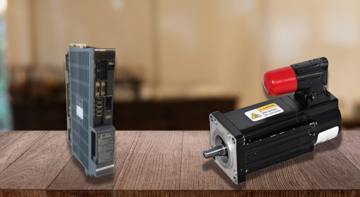
The Drive System
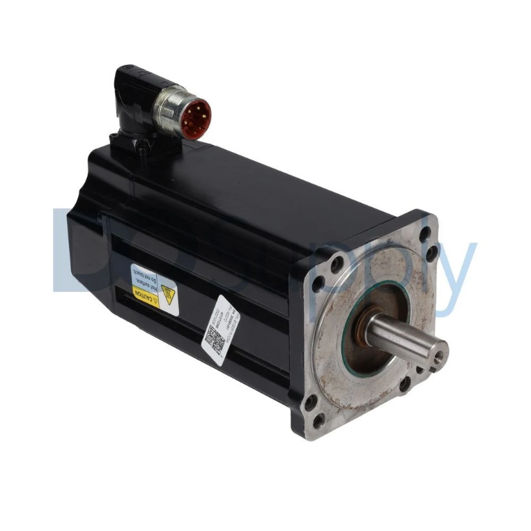
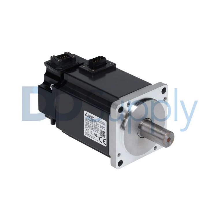
In the drive system, consisting of the use of servomotors, amplifiers, ball screws, and linear guides, the “kinetic engine of precision” is at work. Within the components of the CNC machine, it is the use of a “closed-loop servomotor” versus the “open-loop stepper” motor that is of the highest priority.
In a closed-loop system, the servomotor constantly receives feedback from the amplifier, using the data from the rotary encoder to report the absolute position and velocity in real time. Any deviation, even the effects of load torque, can be immediately corrected.
While the rotary encoder of the motor translates the data through the amplifier, the motor’s rotary output is transformed to linear axis motions by means of a pre-tensioned ball screw. Furthermore, the use of the ball screw, designed with recirculating balls in the nut, allows the screw to achieve efficiency levels above 90% ultimately, there is little heat production, and what is of the highest priority, no backlash is produced. Backlash, the measurable play between the screw and the nut, particularly introduces errors in reversing directions. In the high-precision machine, backlash or play is compensated in software, while the mechanical design emphasizes eliminating backlash through preload and high-quality manufacturing. In the mechanical movements of the machine, the moving components travel on linear guides, which are not mere rails running in a groove, but tracks in precision-ground ‘bearing’ trucks. Additionally, these linear guides ensure precise, low-friction motion in a single geometric plane, fixing all other degrees of freedom so the motion is perfectly straight and flat.
The Spindle
Being the immediate force-applier to the workpiece, the spindle is obviously a high-accuracy focal point. By dynamic rigidity and thermal stability, the spindle’s performance is characterized.
Dynamic rigidity is defined as the spindle’s resistance to deformation during intermittent cutting forces. This is realized through advanced bearing designs, such as matching angular contact bearings in a ‘tandem’ or ‘back-to-back’ arrangement, which are pre-loaded with a certain force to ensure no axial and radial motion.
In this case, the spindle housing may employ thermal decoupling or symmetrical cooling to mitigate heat soak effects emanating from bearing and motor components; otherwise, this would expand the spindle and alter the actual height of the tool’s Z-axis. In high-speed spindles, liquid is circulated internally to maintain a constant temperature. Given the importance of high-precision spindle performance, it is equally important to ensure precise matching accuracy of the tool holder interface, typically in the form of a BT, HSK, or CAT taper. This minor imperfection in cone and flange alignment causes runout, or the variation of tool tip positioning along the actual center of rotation. Micron values of this runout are enough to induce inconsistent tool wear, surface finish, and dimensions.
Feedback System
The feedback loop is where feedback occurs, giving the system self-awareness and making it a closed-loop corrector. Although encoders found on servomotors are of a rotary design, only the top levels of accuracy use secondary, direct measuring systems such as glass scale linear encoders. The glass scales are aligned perpendicular to each axis, measuring the position of either the table or the spindle head directly without relying on information from the ball screw. In this way, any errors caused by potential screw damage, screw expansion due to heat, or very fine backlash are avoided. The controller continuously monitors and measures the desired position requested by the MCU, compares it with the actual position measured by the linear scale, and provides a correction at any given time.
Tooling and Workholding
The accuracy of the most precisely positioned spindle is of no value due to deflection of the cutting tool or motion of the workpiece. Consequently, tooling and workholding solutions represent accuracy-critical components of CNC machines and define their interface. Tool holders have precision-ground tapers and, for HSK tool holders, simultaneous surface and taper contact, ensuring optimal stiffness and accuracy. The use of balanced tool holders eliminates vibration due to centrifugal forces during high-speed machining. On the workholding interface, optimal stiffness remains the primary concern. The vise or workholding fixture must resist forces of several thousand pounds without deflecting and support the workpiece precisely and repeatably. The use of grid plates and doweled precision-machined locators on modular fixturing solutions ensures that a workpiece, once programmed, can be relocated precisely to the same position.
Whatever degree of compliance exists within this chain, whether tool holders, machining tools, work pieces, or fixtures, results in a spring that releases and then accepts this energy, causing unpredictable dimensional accuracy.
Thermal Management and Compensation
Finally, accuracy not only requires initial precision but also must be maintained throughout the production cycle. During machining, the spindle, motor, and machining zone generate heat, causing significant thermal expansion of the CNC machine’s metal parts. Advanced CNC machines can compile thermal expansion data within the CNC system’s control software. The system measures temperature at multiple points embedded within the CNC machine structure, ball screws, and spindle. The system, based on this information, calculates the thermal growth of the system, thereby making an appropriate corrective measure to the axis positions, thereby compensating, for instance, the elongation of the ball screw that is positioned within the x-axis due to the resultant heating caused during the machining operations, thereby maintaining the zero reference point appropriately, due to which the system makes the difference between machining an accurate piece and performing precise production operations during hours.
Conclusion
In other words, the accuracy of a CNC system is itself a complex of engineered solutions. It begins with and is a manifestation of the calculation accuracy of the MCU, is realized through the active, non-backlash motion system, and is supported through the mass of the structure and its ability to damp out vibrations. This motion is, in turn, continuously monitored and corrected by the feedback loop, while the spindle and tools provide support and rigidity to the cutting surfaces. Each of these, in turn, is supported through temperature regulation to guarantee integrity in this dynamic system. Each of these key components of a CNC system, in fact, requires high integrity of design and manufacture, since it is the weakest link in this chain that ultimately delivers system accuracy.
An accurate CNC system relies on quality products you can trust. We at DO Supply carry CNC-centric equipment, such as Allen-Bradley’s VPL motors, Mitsubishi MDS spindle drives, and more. Can’t find what you’re looking for or looking for a repair service for your faulting automation equipment? No problem, reach out to our sales professionals for help! Speaking of automation equipment, we have an article here explaining why most equipment runs on 24V if you’re curious! As always, thank you for reading.
DO Supply Inc. makes no representations as to the completeness, validity, correctness, suitability, or accuracy of any information on this website and will not be liable for any delays, omissions, or errors in this information or any losses, injuries, or damages arising from its display or use. All the information on this website is provided on an "as-is" basis. It is the reader's responsibility to verify their own facts.