How to Extend Drive Life with Proper Cooling and Enclosure Planning
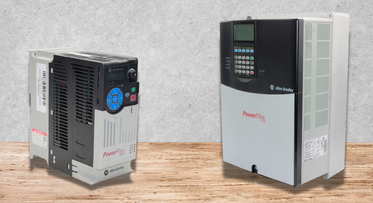
Variable Frequency Drives (VFDs), servo drives, and DC drives are the workhorses of motion control in industrial automation. Their internal semiconductor junctions, IGBTs, power diodes, and electrolytic capacitors, are thermally sensitive. Empirical data from semiconductor reliability models (Arrhenius equation) indicate that a 10°C rise in junction temperature reduces component life by approximately 50%. Conversely, proper thermal management can extend drive life beyond the manufacturer’s 10-year design horizon. This article provides a quantitative framework for cooling and enclosure design specific to drives, focusing on heat load calculation, airflow dynamics, ingress protection (IP) trade-offs, and active versus passive cooling strategies. For engineers responsible for specifying, installing, or maintaining drives, understanding these principles is not optional, it is the difference between a 5-year service life and a 15-year one.
The Thermal Failure Mechanism in Drives
To extend drive life, one must first understand the failure physics. Power electronics within drives dissipate energy as heat due to:
- Conduction losses (I²R across IGBTs and diodes during on-state)
- Switching losses (during turn-on and turn-off transients, proportional to switching frequency)
- Leakage currents (in DC bus capacitors and reverse recovery diodes)
The primary wear-out mechanisms are:
- Electrolytic Capacitor Drying: The DC bus capacitor bank uses a liquid electrolyte. For every 10°C rise above rated ambient (typically 40°C), the evaporation rate doubles, reducing capacitance and increasing ripple voltage. End-of-life occurs when capacitance degrades by 20%. For drives operating continuously at 50°C internal ambient, capacitor life drops from 10 years to approximately 2.5 years.
- Solder Joint Fatigue: Cyclic thermal expansion and contraction (power cycling) induces stress on solder interconnects. Crack propagation follows the Coffin-Manson relationship, accelerating with higher ΔT per cycle. Drives in applications with frequent start-stop cycles (e.g., hoists, reciprocating compressors) experience accelerated failure from this mechanism, independent of average temperature.
- Gate Oxide Breakdown (IGBTs): Elevated temperatures increase leakage current, leading to gate oxide rupture under transient voltage spikes. Once the gate oxide fails, the IGBT cannot turn off, resulting in a shoot-through condition that destroys the drive module.
- Thermal Paste Degradation: The thermal interface material between the IGBT module and heatsink dries out and cracks after extended high-temperature operation. This increases thermal resistance, creating a runaway heating condition.
Thus, cooling is not a convenience, it is a life-extension strategy directly tied to mean time between failures (MTBF). Every 10°C reduction in operating temperature doubles the expected life of the drives.
Heat Load Calculation: Sizing the Cooling System
Before specifying any cooling solution, calculate the total heat dissipated by the drives and other enclosure components. Overestimating leads to unnecessary cost; underestimating leads to premature drive failure.
Drive Heat Loss Data
Manufacturers provide heat loss specifications in watts (or BTU/hr). For drives, a conservative estimate is:
- VFD at full load: 3–5% of rated motor power (e.g., a 10 kW VFD dissipates 300–500 W)
- Servo drives at peak torque: 5–8% of rated power
- Regenerative drives: Higher losses during braking (up to 15% of regenerated power)
- Multi-axis drives: Losses are non-linear; a dual-axis drive typically dissipates 1.8× the heat of a single-axis unit, not 2×, due to shared DC bus and control logic.
Do not rely on nameplate current alone. Use the drive’s efficiency curve at the operating point. Example:
A 22 kW drive operates at 80% load. Efficiency at this point is 97%. Heat loss = 22,000 W × 0.8 × (1 – 0.97) = 528 W.
If switching frequency is increased from 4 kHz to 8 kHz, switching losses double. Add 15–20% to the calculated heat loss for every doubling of switching frequency above the manufacturer’s baseline.
Total Enclosure Heat Load
Sum the losses from:
- All drives (including derating for switching frequency)
- Control transformers (typical loss: 5–10% of VA rating)
- Power supplies (linear supplies: up to 40% loss; switching supplies: 10–15% loss)
- PLCs and I/O modules (estimate 5–15 W per module)
- Internal lighting and panel fans (add fan motor heat to load)
Use this total (Q_total, in watts) to size cooling. For enclosures with significant solar gain (outdoor installations), add 50–100 W/m² of exposed surface area.
Enclosure Cooling Strategies for Drives
Enclosures protect drives from contaminants, but they also trap heat. The choice of cooling method depends on Q_total and the enclosure’s surface area.
Natural Convection (Passive Cooling)
- Applicable when: Q_total ≤ 100 W and enclosure volume ≤ 0.5 m³.
- Mechanism: Heat transfers from drive heatsinks to internal air, then through enclosure walls to ambient. The enclosure must be metallic (steel or aluminum) with external fins or unpainted surfaces to maximize emissivity (ε ≈ 0.85 for oxidized aluminum).
- Design rule: Provide 0.12 m² of exposed surface area per 10 W of dissipation. Mount drives on a backplate that is thermally bonded to the enclosure rear wall (use thermal paste at contact points). For backplate thickness, use minimum 5 mm aluminum or 6 mm steel, thinner material introduces thermal resistance.
- Limitation: Ineffective when ambient temperature exceeds 40°C or when drives are stacked vertically (hot air stratifies). Passive cooling also fails in still-air conditions; natural convection requires a minimum vertical temperature gradient to drive airflow.
Forced Convection (Filtered Fans)
- Applicable when: 100 W < Q_total < 500 W, and the environment is relatively clean (IP20 to IP54).
- Mechanism: A fan (typically 120–230 VAC or 24 VDC) moves air across the drives. Filtered intake prevents dust ingress, but filters increase pressure drop.
Critical calculations:
- Static pressure: Must overcome filter resistance (typical 20–40 Pa for a clean filter) and louver resistance. Undersizing pressure leads to motor stall and overheating. Use the fan’s PQ curve, not just maximum CFM.
- Air velocity across drives: Minimum 2 m/s across heatsink fins for effective heat transfer. Verify with anemometer.
- Failure mode: Clogged filters reduce airflow by 70% within 3 months in dusty environments. Install differential pressure switches with alarm outputs to trigger filter cleaning. For drives in cement or woodworking facilities, consider self-cleaning filters or cyclonic pre-filters.
Air-to-Air Heat Exchangers (Closed-Loop)
- Applicable when: Environment is dirty, humid, or corrosive (IP54 to IP66 required), and Q_total < 1000 W.
- Mechanism: Internal fan circulates hot air over a finned core; external fan passes ambient air over the opposite side. No outside air enters the enclosure. The core separates the two airstreams.
- Selection criterion: Manufacturer-provided heat transfer rate (W/°C). For a 10°C internal-to-ambient differential, a heat exchanger rated at 50 W/°C removes 500 W. For a 20°C differential, the same unit removes 1000 W.
- Advantage for drives: Eliminates condensation risk. Drives are sensitive to moisture on circuit boards, which causes electrochemical migration and short circuits. In coastal or high-humidity environments, heat exchangers are superior to fan-and-filter systems.
- Disadvantage: Cannot cool internal temperature below ambient. If ambient exceeds 40°C, the internal temperature will be at least 40°C plus the exchanger’s differential.
Air Conditioners (Active Refrigeration)
- Applicable when: Q_total > 500 W, ambient exceeds 45°C, or internal temperature must stay below 35°C for electrolytic capacitor longevity.
- Mechanism: Vapor-compression cycle (compressor, condenser, evaporator, expansion valve) actively pumps heat to ambient even when ambient is hotter than the enclosure interior. Coefficient of performance (COP) typically ranges from 1.5 to 2.5.
- Sizing: Match the air conditioner’s cooling capacity (W or BTU/hr) to Q_total at the maximum expected ambient. Oversize by 15–20% to account for compressor duty cycle. Do not oversize beyond 30%, short-cycling reduces compressor life.
- Critical consideration for drives: Air conditioners produce condensate. Ensure the drain line is routed below the enclosure and fitted with a trap to prevent hot, humid air from backing in. Mount the unit so cold air does not blow directly onto drive electronics (causes localized condensation). Use an air duct to mix cold air with internal air. For drives in food processing or pharmaceutical environments, use stainless steel air conditioners with coalescing filters.
Enclosure Layout Best Practices for Drives
Poor layout negates even the best cooling system. Follow these rules:
Vertical Stacking Prohibition
Drives should never be mounted directly above one another without a horizontal baffle. Hot air rising from the lower drive enters the upper drive’s intake, raising its ambient by 10–15°C. Maintain 150–200 mm vertical clearance between drives. For side-by-side mounting, allow 50 mm minimum. For drives mounted in rows, stagger them vertically so the upper drive overhangs the lower by 30 mm, creating a chimney effect.
Heatsink Orientation
Most drives are designed for vertical mounting with heatsink fins running vertically. This allows natural convection to assist forced airflow. Horizontal mounting reduces effective cooling area by 40% and creates hot spots at the upper end of the heatsink. If horizontal mounting is unavoidable, derate the drive current by 25%.
Airflow Path
Design a U-shaped or Z-shaped airflow pattern:
- Intake: Lower left or lower front (cool air)
- Exhaust: Upper right or top (hot air)
- Obstructions: Route wire ducts away from drive intake vents. A wire duct placed 20 mm in front of a drive fan reduces airflow by 30%.
Airflow balance: Measure pressure differential between intake and exhaust. For every 25 Pa of negative pressure inside the enclosure, airflow decreases by 15%. Use bleed vents or secondary intakes to balance.
Final Thoughts
In conclusion, extending drive life is a quantitative engineering exercise. The Arrhenius model is unforgiving: every degree above specification increases the risk of failure. Proper cooling begins with accurate heat load calculation, proceeds through strategic enclosure layout, and ends with continuous monitoring. For drives operating in harsh or high-ambient environments, closed-loop cooling (heat exchangers or air conditioners) is not an expense; it is an investment in uptime. Ignore thermal planning, and drives will fail at the worst possible moment, taking production with them. Respect the thermal limits specified in the datasheet, implement a maintenance schedule for filters and fans, and the drive will return years of reliable service. We do have an article here that goes more in-depth on IP ratings and cooling. The cost of a well-cooled enclosure is trivial compared to a single unplanned production stoppage. Plan accordingly.
If all else fails, there is always hope. We at DO Supply offer repair services for failed automation equipment. We are also a large source of parts, replacements, and upgrades. If this seems like something you would like, feel free to stop by our site or contact our support team for more information!
DO Supply Inc. makes no representations as to the completeness, validity, correctness, suitability, or accuracy of any information on this website and will not be liable for any delays, omissions, or errors in this information or any losses, injuries, or damages arising from its display or use. All the information on this website is provided on an "as-is" basis. It is the reader's responsibility to verify their own facts.