Replacing Pushbutton Panels with an HMI: What Changes and What Doesn’t?
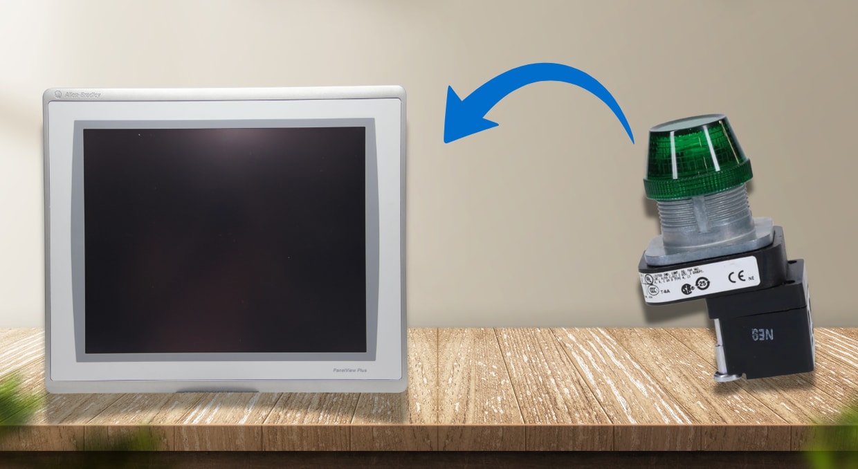
The question of whether to replace the row of pushbuttons and selector switches on the HMI eventually arises on practically every classic machine or control panel. One touchscreen rather than twenty separate devices seems like a straightforward surface-level alternative. The engineering response is far more complex. The way the operator interface is wired, how PLC logic processes inputs, how data is logged, and how alerts are displayed are some of the key changes. Everything else that comes into contact with the hardwired safety circuit must remain unchanged. The difference between a clean migration and one that results in unexplained PLC logic rewrites, or safety compliance problems mid-commissioning, is to formally distinguish between these two groups before the project begins.
What Does a Pushbutton Panel Actually Do?
Before discussing what changes, it helps to be precise about what a pushbutton panel is doing at the wire level. Each pushbutton, start, stop, jog, and mode select wires a physical contact directly to a PLC discrete input module. A 24 VDC sourcing input module sees +24 VDC on the input terminal when the button is pressed, reads the bit high, and the ladder logic acts on it. Pilot lights are wired to the discrete output terminals and illuminate when the output bit is energized. The entire interface resolves at the I/O module layer: no communication protocol, no scan-cycle delays beyond the PLC’s own I/O update, no software tags in between. A typical hardwired architecture on a ControlLogix system has start/stop pushbuttons, hand/auto mode selector, and home/limit sensors all wired to the digital input module, for example, a 1756-IB32, with direct wire connections to specific input bits. That electrical reality is what the HMI migration replaces.
What Changes: I/O Wiring and PLC Tags
The most significant electrical change when replacing a pushbutton panel with an HMI is that discrete input wiring for operator-initiated commands is no longer necessary. A Start button that was previously wired to I:0/3 on a 1746-IB16 module becomes a momentary pushbutton object on the HMI screen that writes the BOOL tag Conveyor_Start_CMD to the PLC over EtherNet/IP. The ladder logic that examined I:0/3 now examines that tag. Pilot lights that consumed discrete output terminals now read PLC status tags and change color on the screen.
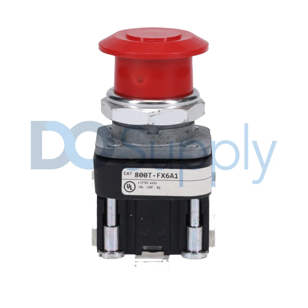
The specific items eliminated from the panel wiring schedule include:
- Start, stop, and jog pushbuttons with contact blocks
- Hand/Off/Auto and Local/Remote selector switches
- Normally-open and normally-closed auxiliary contacts for interlocking
- Pilot lamp holders, lamp assemblies, and LED indicator modules
- All associated 22mm cutouts, legend plates, and terminal block connections
This restructuring carries a logic implication. An HMI button writing a BOOL tag holds that bit high for as long as the operator’s finger contacts the screen, typically 100–300 ms, depending on the HMI’s tag write update rate. Logic using the input bit as a sealing contact in a seal-in rung must be reviewed. The HMI write duration may not match the assumption built into the original logic structure, and a one-shot (ONS) instruction on the HMI command tag is the correct resolution in most cases.
What Doesn’t Change: The Hardwired Safety Circuit
This is the non-negotiable boundary of any HMI migration. E-stop must be a physical, hardwired safety circuit. An HMI cannot drive E-stop functionality per IEC 60204-1; this is a firm regulatory boundary, not a design preference. The E-stop mushroom head wires directly to a safety relay, Pilz PNOZ, Allen-Bradley MSR, Siemens 3SK1, and the safety relay’s output contacts break the motor contactor coil circuit through a purely hardware path. No PLC scan, EtherNet/IP transaction, nor HMI tag write is in that path.
The following must remain hardwired regardless of how comprehensive the HMI migration is:
- Emergency stop buttons wired to dual-channel safety relay inputs
- Safety door interlocks and light curtain OSSD outputs wired to safety relay or safety PLC inputs
- Safety relay output contacts hardwired in series with motor contactor coils or drive STO inputs
- Physical reset pushbutton hardwired to the safety relay reset terminal, where Category 3/PLd or higher is required
The safety relay itself must be hardwired to the E-stop circuit with no software intervention in the trip path. Only the reset function may be performed via software; the fault trip mechanism must remain purely hardware-based. The safety relay auxiliary contact wires to a PLC digital input for monitoring only. Log each transition and show ElectronicStop_Active on the HMI with a large red banner. When ElectronicStop_Latch is TRUE, stop scripted sequences from initiating. All of this enhances plant security by providing operators with clear information about what is happening, but it cannot substitute for the hardware safety process.
Communication Architecture: EtherNet/IP Tag Transactions
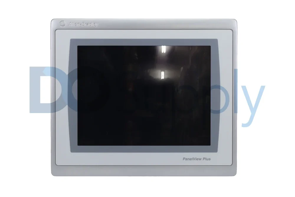
The connection between operator intent and PLC execution shifts from a copper wire to a protocol transaction when the HMI serves as the pushbutton panel I/O. A PanelView Plus 7 or PanelView 5510 on a Rockwell-based system uses CIP messaging to communicate over EtherNet/IP with a ControlLogix or CompactLogix processor. Any HMI object relates to a certain controller tagname. When an operator interacts with a control element, the HMI writes command tags and polls status tagnames for displaying updates.
Key parameters to configure and verify at commissioning:
- Display tag update rate: 200–500 ms is sufficient for most process and conveyor applications
- CIP connection count: verify the PanelView does not exceed the processor’s connection limit, 128 connections for a 1756-EN2T/B at firmware v20+
- Connection health watchdog: implemented in PLC logic to detect HMI communication loss and force run permissives FALSE on timeout
For applications where the original pushbutton panel was used for high-frequency jogging or rapid positioning, the latency introduced by the HMI tag-write path must be evaluated against the application’s response requirement. In those cases, a physical jog button wired to a discrete input is retained, not as redundancy but as the functionally correct input for that specific operation.
PLC Logic Restructuring: Mode Selection and Interlocks
Mode selection is performed via pushbutton panels with selector switches, which send discrete input bits directly into ladder logic. When they are taken out for HMI selections, the PLC must manage similar mode control through tags, which often shows logic that was never neatly organized in the original program. The PLC logic must control fault management and alerting across all input sources, handle mode selection with HMI override inhibit in hand mode, and interlock start/stop between hardwired and HMI instructions. In the context of HMI, the three-wire control approach also requires an update. Because a communication failure leaves the tag in its final condition rather than deactivating the output, an HMI stop button writing a Boolean tagname to 0 is not equivalent to a hardwired NC stop contact. In the event that the HMI communication link is lost, the PLC program must continue monitoring the CIP connection status tag and use it to force the run permissive to FALSE. A tag-based stop command is sufficiently safe to serve as the primary operator stop function for non-security-critical outputs due to this single modification.
What the HMI Adds: Alarms, Logging, and Access Control
This is where the HMI unambiguously exceeds what a pushbutton panel provides. Data logging and recipe management are standard HMI capabilities, stored production data supports historical analysis and compliance, and pre-configured parameter sets ensure repeatable process outcomes. In regulated industries, this must meet FDA 21 CFR Part 11 requirements for electronic records and signatures.
The operational improvements over a pilot light panel are concrete:
- Alarm timestamps: Every fault is time-stamped at first occurrence, giving maintenance the sequence of events rather than just the present state.
- Acknowledgment tracking: The HMI can record who acknowledged an alarm and when, giving maintenance and supervisors a level of accountability that a horn-and-reset-lamp setup cannot provide.
- Historical trending: Process variables such as motor current, speed reference, and temperature are trended and reviewed without a separate historian.
- Recipe management: Parameter sets for different product runs are stored and recalled without manual entry at individual devices.
- User access levels: Operator, supervisor, and maintenance roles are enforced by HMI login, preventing unauthorized parameter changes that a physical selector switch cannot restrict.
On a multi-motor system with sequential interlocking, the alarm timestamp record is the difference between a ten-minute fault diagnosis and a two-hour one.
Environmental and Mounting Considerations
Environmental protection is often the first filter in HMI selection. An HMI that cannot survive its installation environment will fail regardless of its other capabilities. Pushbutton panels with 22mm devices are typically IP65-rated as assembled. The HMI replacement must carry an equivalent or better display rating. Most HMI models are IP65/NEMA 4, CE, and RoHS certified, making them suitable for harsh industrial settings. In washdown environments, food processing, beverage, and pharmaceutical applications require IP66- or IP69K-rated displays with stainless steel bezels.
Additional installation factors specific to HMI replacement:
- The panel cutout is larger than a cluster of 22mm buttons and may require door reinforcement
- High-bay or outdoor installations require sunlight-readable displays at a minimum 1,000 nit brightness to prevent glare-related readability failures
- HMI communication cable conduit entries must be separated from AC power wiring to prevent noise-induced communication errors
- Internal enclosure temperature must be verified against the HMI’s operating range, typically 0–55°C, not just the ambient room temperature
Final Thoughts
In conclusion, the I-O wiring design, PLC tag architecture, and information provided during problem diagnostics are all modified when an HMI replaces a pushbutton panel. The hardwired safety circuit, which continues to be the Electronic stop to the safety relay to the contactor with the PLC and HMI monitoring status alone, is unaffected by any of that. Maintain a clear distinction between those two categories: everything that was a discrete operator I/O becomes an EtherNet/IP tag transaction and benefits from it, while whatever was a hardwired safety function remains hardwired and must never become a tag write.
An HMI can replace a row of buttons, but it should never replace good engineering judgment. If you are upgrading an older pushbutton panel, we at DO Supply can help you find the right HMI, replacement controls, safety components, and supporting hardware for the job. Give us a call today and let us help you modernize your operator station. If you would like to learn more about PanelView HMIs, we have an article going over their performance in harsh environments here.
DO Supply Inc. makes no representations as to the completeness, validity, correctness, suitability, or accuracy of any information on this website and will not be liable for any delays, omissions, or errors in this information or any losses, injuries, or damages arising from its display or use. All the information on this website is provided on an "as-is" basis. It is the reader's responsibility to verify their own facts.