What Causes Nuisance Overcurrent Faults on PowerFlex Drives?
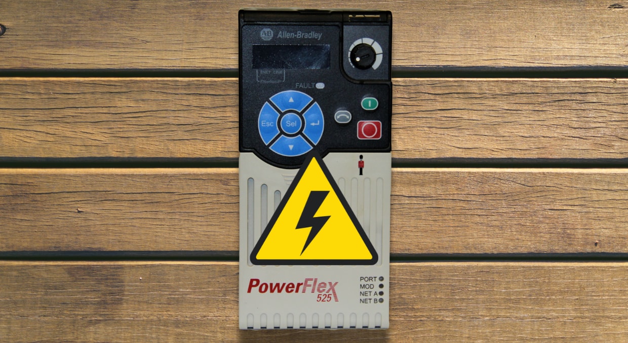
One of the most annoying diagnostic situations in industrial drive maintenance is a nuisance overcurrent issue. When the PowerFlex trips, production stops, the operator resets it, and it functions normally for many hours before tripping again for no apparent reason. Nuisance overcurrent faults are condition-dependent, sporadic, and seldom self-explanatory from the fault code alone, in contrast to a hard fault brought on by an obviously malfunctioning component. An overcurrent fault is a precise diagnostic signal intended to prevent damage to the motor, drive, and related equipment. It shows up as a strong, abrupt current spike that exceeds the drive’s hardware limits. Diagnosing any PowerFlex model, from the tiny 525 to the architecture-class 755T, depends on understanding what causes these spikes and distinguishing between hardware-level and software-level overcurrent detection.
Hardware Overcurrent vs Software Overcurrent
When diagnosing a PowerFlex overcurrent problem, the first thing to consider is whether the event is software or hardware overcurrent, as each has separate causes, thresholds, and diagnostic pathways. When the drive observes 220 to 300% of its output current rating, the F12 Hardware Overcurrent safety mechanism, which is integrated into the transistor part of the drive and functions independently of software, is usually activated. Firmware controls software overcurrent (F007 on most PowerFlex models), which reacts to persistent overcurrent exceeding the motor nameplate threshold for a predetermined period. The practical division is straightforward: F012 refers to cables, motor windings, gate drivers, IGBTs, and physical hardware. F007 refers to current limit settings, acceleration ramp arrangement, motor FLA entry, and parameters. Misidentifying the fault wastes diagnostic time and risks replacing components that are functioning correctly.
Incorrect Motor Nameplate Parameter Entry
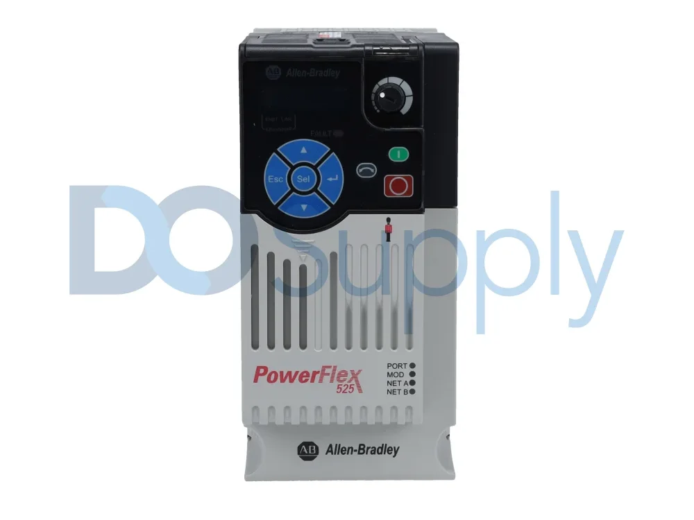
The most common reason for annoying F007 software overcurrent excursions is incorrect FLA input. An inaccurate entry shifts the trip point away from the motor’s actual operating range because the drive’s protection threshold is set directly by the motor rated current parameter. This is the most common cause for newly commissioned drives or drives with adjusted specifications. Before beginning any further diagnostic procedure, confirm that the motor nameplate data, FLA, voltage, RPM, and Hz precisely match the driving parameters. Motor NP FLA, Motor NP Volts, Motor NP Hertz, Motor NP RPM, and the Current Limit setting are crucial characteristics to verify. Excessive restrictions put the motor and drive at risk of damage, while overly conservative current limit settings cause annoying excursions. To let the drive identify motor characteristics accurately without load interference distorting the measurement, run Autotune with the load completely disconnected from the motor shaft after any parameter corrections.
Acceleration Ramp Times Set Too Short
One of the most common causes of annoying overcurrent problems in production settings is an acceleration ramp time that is too short for the combined inertia of the motor and driven load. Even on healthy drives with appropriately rated motors, excessively aggressive ramps command current at rates that exceed overcurrent thresholds. Check the acceleration and deceleration time settings to ensure sufficient ramp durations for the load inertia. Instead of copying an earlier application, calculate the proper acceleration time using the load’s moment of inertia and the required speed change. Compared to low-inertia pumps, high-inertia loads like fans, centrifuges, and flywheel presses require significantly longer ramp times. Other diagnostic symptoms include the fault occurring consistently at a certain location during acceleration, rather than during steady-state operation.
Mechanical Binding and Sudden Load Spikes
When a mechanically driven load jams, seizes, or encounters unexpected resistance, it creates an instantaneous torque demand that immediately causes a current spike at the drive output. Before looking into electrical reasons, check for and minimize excess load. These fault codes often indicate mechanical binding in the system, where even a small increase in load speed can cause an overcurrent problem. Mechanical causes to investigate include product jams in packaging or conveying applications, shaft misalignment causing cyclical torque variation at rotational frequency, seized or worn bearings producing intermittent high-friction events before complete failure, and cracked gear teeth producing sharp torque impulses once per revolution. To identify the precise source of the current spike, run the motor uncoupled from the driven load and confirm the current stays within the nameplate range before gradually reconnecting the mechanical system.
Long Motor Cable Runs and Capacitive Charging Currents
Due to the high dV/dt of PWM switching, motor cables longer than 50–100 meters between a PowerFlex drive and its motor introduce two different overcurrent processes. We have a deeper dive into how cable length affects AC Drive here. The first is capacitive charging current, which causes transient current pulses at the output terminals that current-detecting circuits interpret as overcurrent events even though no overcurrent flows through the motor windings. Distributed cable capacitance charges and discharges on each PWM switching edge. Install an output reactor or dV/dt filter on cable lines longer than 100 meters to stop annoying trips caused by capacitive charging currents. Progressive insulation deterioration under repeated high-voltage PWM stress is the second process. Disconnect the motor cables at the drive output and megger-test each phase to ground to verify both. All readings must be above 1 MΩ; values below this threshold indicate insulation deterioration and require replacing the cable or motor before re-energizing the drive.
IGBT Degradation and Progressive Power Module Failure
Hardware Overcurrent F0012 usually denotes severe output short-circuit circumstances, gate driver malfunction, or IGBT failure. Component-level repair requires identifying the failing power module and then testing the IGBTs. This defect frequently arises from gradual IGBT deterioration caused by thermal cycling, voltage transients, or prior overcurrent stress. IGBT deterioration is not an abrupt failure, but rather a wear-out mechanism. The desaturation threshold gradually drops due to repetitive thermal cycling, bond wire degradation, and solder-layer cracking, and the drive trips at current levels it previously handled flawlessly. Using a multimeter in diode test mode, measure the difference between each output phase (U, V, and W) and the positive/negative DC bus. On healthy IGBTs, forward bias should be between 0.3 and 0.7 V; shorter values indicate IGBT failure. The problem occurring at increasingly decreasing loads and F012 tripping at no load with no mechanical explanation are important signs.
False Trips from Current Sense Circuit Failure
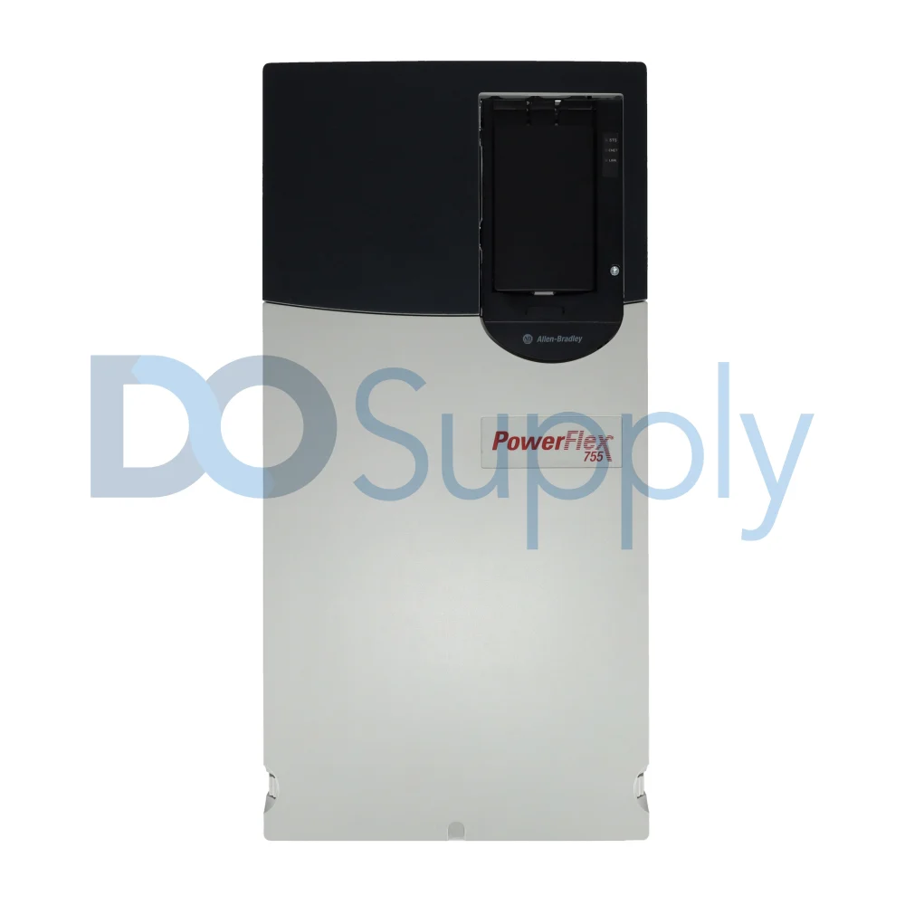
A malfunction in the drive’s current-detecting hardware is a unique failure condition that generates overcurrent faults without any real overcurrent in the output circuit. A malfunction in the current-detecting hardware, such as Hall-effect sensors or shunt resistors with amplification, might cause false overcurrent detection that fault codes alone cannot distinguish from a real overcurrent event. The defect is unique in that it occurs with no load attached and no current flowing, making actual overcurrent physically impossible. The current-sensing circuit or signal-conditioning board between the sensors and gate driver is the main suspect if a PowerFlex drive trips F012 on a run command without a motor or wires attached to its output terminals. Instead of requiring replacement of the entire power section, fault diagnostic data on modular PowerFlex 755 setups identifies which power module triggered the overcurrent condition, isolating the issue to one phase.
Supply Voltage Disturbances and DC Bus Transients
Overcurrent failures are caused by supply-side voltage disturbances through a process that is not immediately apparent: transients on the AC input create matching events on the DC bus, temporarily changing the motor flux state and producing a transient output current spike. When the PowerFlex drive is coupled to distribution transformer secondary windings configured as ungrounded, high resistive ground, or corner-grounded delta, the chance of drive problems increases, including overcurrent. Voltage sag below 85% of nominal forcing higher output current to maintain torque, input phase loss causing DC bus ripple and output current asymmetry, and large motor starters or capacitor banks switching on the same feeder producing transients that couple through the rectifier bridge into the DC bus are examples of supply conditions causing nuisance overcurrent. By adding a 1-3% impedance line reactor to the PowerFlex AC input, the line reactor absorbs switching-event energy and reduces the transient magnitude that reaches the bus.
Final Thoughts
In conclusion, when you follow the proper procedure, you can thoroughly diagnose PowerFlex drive nuisance overcurrent issues. The diagnostic field is quickly narrowed by separating hardware from software. In just a few minutes, parameter verification removes the most common cause. Supply quality monitoring, mechanical load separation, IGBT diode testing, and cable insulation testing methodically address every remaining cause. The problem that resets and runs for a week before coming back is not random; it is waiting for a certain operating state to trigger the recurrence. A persistent production disruption can be transformed into a maintenance activity that is permanently fixed by identifying that situation through systematic inquiry, as opposed to recurrent resets.
DO Supply Inc. makes no representations as to the completeness, validity, correctness, suitability, or accuracy of any information on this website and will not be liable for any delays, omissions, or errors in this information or any losses, injuries, or damages arising from its display or use. All the information on this website is provided on an "as-is" basis. It is the reader's responsibility to verify their own facts.