Thermal Management in PowerFlex Drive Cabinets
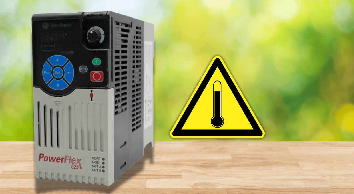
The most important technical discipline in the design of PowerFlex drive cabinets is thermal control. From the little 523 to the architecture-class 755T, every PowerFlex drive loses some of the electricity it processes as heat within the cabinet enclosure. If the heat isn’t actively controlled, it builds up in the enclosure air, raises the internal ambient temperature above the drive’s specified operating range, and causes the drive’s temperature-sensitive parts to wear out faster. According to the Arrhenius equation, a 10°C increase in operating temperature halves the service life of DC bus capacitors. This connection is exponential. Correct thermal management during cabinet design is the main factor that determines a drive’s lifespan, not a quality-of-life enhancement.
Quantifying the Heat Load
The first step in any PowerFlex cabinet thermal design is to figure out how much heat each component within the enclosure dissipates. A 30 HP (22.4 kW) PowerFlex 70 dissipates around 0.67 kW as heat, computed as 30 HP × 0.746 kW/HP × 0.03 efficiency loss, since PowerFlex drives are normally 97% efficient at full load. At full load, a cabinet with four of these drives dissipates about 2.68 kW continuously. Add heat from line reactors, control transformers, brake resistors, PLC power supplies, and any other heat-producing parts that share the enclosure to this number. The thermal load that the cooling system must eliminate to maintain the internal ambient temperature within the drive’s rated working range is represented by the total wattage value.
The Arrhenius Relationship and Why Temperature Matters
The rate at which each electrolytic component in a PowerFlex drive degrades is determined by the Arrhenius equation. The rule is straightforward for DC bus capacitors, which are the parts most sensitive to temperature: every 10°C rise in operating temperature reduces service life by half, and every 10°C reduction doubles it. If the enclosure interior temperature continuously operates at 60°C instead of 50°C, the capacitor life of a PowerFlex 525 certified for continuous operation up to 50°C without derating will be halved. Because of this link, enclosure thermal management becomes both a capital cost and an operational issue. Inadequate cooling reduces the time between costly drive replacements by a factor that can be accurately calculated from the temperature difference.
PowerFlex Drive Temperature Ratings and Derating
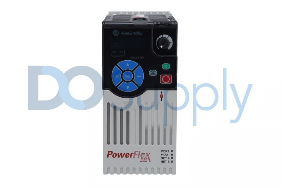
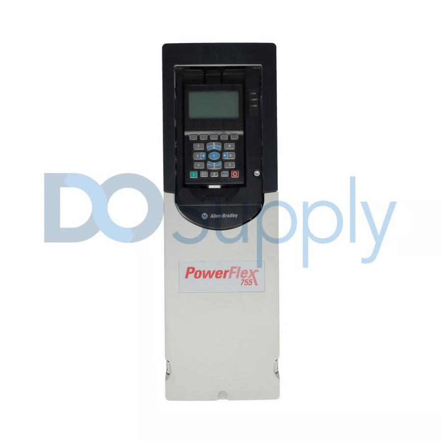
In order to keep component temperatures from rising over acceptable limits, each PowerFlex model provides a maximum ambient temperature rating above which the drive must be derated, and its output current lowered. With an optional control module fan kit and current derating, the PowerFlex 525 may run in temperatures as high as 70°C. It is certified for continuous operation up to 50°C without derating. According to the established derating curves in publication 750-TD001, derating is applied above the 40°C ambient temperature assumed by the PowerFlex 755 standard ratings. Drive derating in a thermally insufficient enclosure indicates poor thermal design that simultaneously lowers the drive’s usable output capacity and accelerates component aging; it is not a safe operating state.
Natural Convection Cooling: When It Is and Is Not Sufficient
Only extremely low heat loads in cold ambient surroundings may benefit from natural convection cooling, which relies on conduction and radiation through the enclosure walls to remove heat to the surrounding air. A helpful empirical guideline for sealed enclosures with PowerFlex drives is that, for comparable thermal performance, the enclosure volume should be around 4× the NEMA 1 vented package volume. This translates to a minimum interior capacity of around 3,400 cubic inches for sealed natural convection cooling at typical ambient conditions for a single Frame D PowerFlex 70 30HP drive. Regardless of enclosure size, active cooling is required when many drives share a single cabinet because the cumulative heat load quickly surpasses what natural convection can remove.
Forced Air Cooling: Fan Selection and Placement
The most economical thermal management option for enclosures when natural convection is inadequate, but the environment allows filtered ventilation apertures, is forced-air cooling using panel-mounted fans. Active forced-air cooling is necessary to keep the interior temperature of nine PowerFlex 525 drives, which dissipate around 2.7 kW of heat, below 40°C at an ambient temperature of 20°C. Basic thermodynamic concepts govern fan placement: cold air enters at the bottom of the enclosure, and exhaust air leaves at the top, driven by both the fan and the heated air’s natural buoyancy. The most efficient airflow route over all heat-generating components is created when the inlet and exhaust fans are diagonally opposed, with the intake at the bottom front and the exhaust at the top rear.
Air Filter Selection and Maintenance Intervals
Inlet air filters are necessary for any forced-air-cooled PowerFlex cabinet to keep dust, conductive particles, and airborne pollutants from building up on PCB surfaces and drive heatsinks. A filter with too-fine a mesh causes excessive pressure drop, lowering airflow below the design requirement. In contrast, a filter with too-coarse a mesh lets particles pass through, deposit on heatsinks, and reduce cooling effectiveness. Therefore, the filter choice must balance airflow restriction and particle-capture efficiency. In particular, PowerFlex 525 technical guidelines advise checking integrated fan functioning and sweeping dust from drive heatsink fins at certain intervals. The most frequent source of avoidable overtemperature drive problems is clogged filters, which are prevented by quarterly examination and condition-based filter replacement.
Heat Exchanger Cooling for NEMA 4/12 Enclosures
Forced-air ventilation is not an option when the installation environment requires NEMA 4 or NEMA 12 sealed enclosures, washdown, outdoor, or high-contamination settings; therefore, a sealed heat exchanger or vortex cooler must be provided. A heat exchanger removes the estimated heat load while preserving enclosure integrity by transferring heat from the interior enclosure air to the exterior ambient air through a sealed aluminum matrix. A heat exchanger rated for at least 3.2 kW at the maximum ambient temperature difference provides the necessary 20% safety margin for a completely enclosed NEMA 4/12 cabinet with four 30HP PowerFlex 70 drives producing 2.68 kW. Enclosure heat exchangers that work with the typical cabinet mounting designs used in PowerFlex installations are produced by Hoffman, Hammond, and Rittal.
Liquid Cooling for High-Power PowerFlex Applications
Liquid cooling becomes the recommended thermal management strategy for PowerFlex drives beyond around 200 HP, since air cooling becomes unfeasible in small enclosure footprints. A chillplate, a liquid-cooled cold plate that is directly connected to the IGBT module mounting surfaces, takes the role of the typical air-cooled heatsink in the PowerFlex 755 with OEM Liquid Cooling Frame 6 and 7. O-ring face-seal connections with 3/4-inch nominal SAE dash-size fittings are used for coolant intake and outlet connections, and a thermal switch is added to the DC inductor for added protection. With a cooling-loop interlock that halts the drive if coolant flow falls below the minimum level detected by the flow switch on the intake connection, the PowerFlex 700L is designed as a liquid-cooled platform.
Thermal Stratification and Hot Spot Management
Thermal stratification, the tendency of hot air to build up at the top of an enclosure while cooler air pools at the bottom, creates localized hot spots that unevenly harm drive components even in an appropriately sized, cooled enclosure. Because it pulls air that has already been heated by all the components below it, a PowerFlex drive installed at the top of a cabinet sees a much greater input air temperature than a drive installed at the bottom. The topmost drive in a multi-drive cabinet always runs hotter and dies sooner than drives below in the same enclosure. This stratification effect is eliminated, and the thermal load is distributed uniformly across all installed drives by routing cooling airflow vertically through the enclosure using baffles that funnel fresh incoming air past each drive in parallel rather than in series.
Braking Resistors: The Hidden Heat Source
One of the heat sources that PowerFlex cabinet thermal calculations most often ignore is braking resistors. The brake resistor dissipates the motor’s kinetic energy as heat during each deceleration event in applications that often decelerate, such as conveyors, hoists, and centrifuges. Although this heat is sporadic rather than continuous, in high-duty-cycle situations, the brake resistor’s average power dissipation may match or exceed the drive’s steady-state heat dissipation. Braking resistors must never share the PowerFlex cabinet’s sealed interior volume and must always be installed outside of the main drive enclosure, either outside or in a separate vented enclosure. In a high-duty-cycle application, a 2 kW peak-dissipation brake resistor installed within the drive cabinet may raise the interior temperature above the drive’s operational limit within minutes.
Monitoring Drive Temperature Through Built-in Diagnostics
Through its diagnostic parameter set, every PowerFlex drive offers real-time heatsink temperature monitoring. For example, Parameter 92 on the PowerFlex 525 delivers drive temperature as a live value that can be viewed via the EtherNet/IP network or the keypad. Using real thermal history rather than predetermined calendar intervals, the PowerFlex 755T’s TotalFORCE technology continually assesses remaining component life, including the cooling fan, and notifies maintenance teams when fan replacement is required before the next overtemperature fault. Before the temperature reaches the drive’s protection threshold and causes an unplanned shutdown, trend analysis can detect progressive enclosure cooling degradation, gradual filter loading, or a gradual decrease in fan speed by integrating drive temperature parameters into the SCADA or DCS historian.
Final Thoughts
In conclusion, thermal management for PowerFlex drive cabinets is a quantitative engineering discipline. Each installation requires a calculated heat load, a cooling technique that matches that load and the enclosure IP rating, proper component placement to avoid hot spots, brake resistor isolation, and a planned maintenance schedule for filters and cooling fans. The Arrhenius relationship, which states that every 10°C of excess temperature halves service life, makes the effects of poor thermal management exact and predictable. A PowerFlex drive will consistently reach or surpass its stated design life provided it is properly mounted in a thermally engineered cabinet and serviced on a planned cooling system check interval. A drive in a small, poorly ventilated, or poorly maintained enclosure will likely fail early due to heat rather than a flaw. Temperature considerations aren’t only for drives; PanelViews are also temperature-sensitive. Check out our guide here!
For all of your drive needs, visit us at DO Supply. We carry different drives from brands you know and trust. We also offer our own repair services if your drive has cooked in an improperly vented enclosure, or just doesn’t want to work anymore. We are also an excellent source for other automation equipment, such as PLCs, photo eyes, motors, and more. Call or email our sales team today and let us help you bring life into old drives or find replacements.
DO Supply Inc. makes no representations as to the completeness, validity, correctness, suitability, or accuracy of any information on this website and will not be liable for any delays, omissions, or errors in this information or any losses, injuries, or damages arising from its display or use. All the information on this website is provided on an "as-is" basis. It is the reader's responsibility to verify their own facts.