How PowerFlex Drives Handle Overload Conditions Without Tripping Your Line
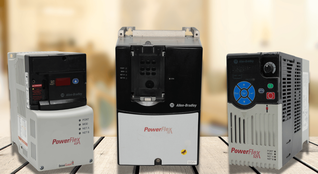
PowerFlex variable frequency drives help reduce annoying tripping during extreme mechanical overloads, which helps control industrial motor loads. Heavy industrial processes often face jams, high-inertia starts, and abrupt torque surges. A PowerFlex drive uses dynamic voltage control, advanced thermal modeling, and active current limiting instead of instantly shutting down to protect hardware. These integrated control systems let the drive withstand brief overloads and enable continuous motor operation. By understanding how a PowerFlex drive handles high-current demands, system engineers can maximize plant uptime, protect mechanical connections, and avoid costly production-line shutdowns during unexpected surges.
Thermal Motor Modeling and Overload Algorithms
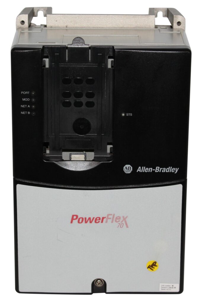
All PowerFlex drives have sophisticated internal thermal memory algorithms that determine motor heating in real time without the need for external temperature sensors. The drive determines the thermal condition of the power semiconductor switches and the motor windings by tracking stator current output over time. An electronic overload protection curve based on standard I^2 t thermal characteristics is used by the PowerFlex control system. The inbuilt accumulator monitors the accumulation of thermal stress when current surpasses nominal levels. This proactive monitoring lets the PowerFlex drive dynamically adjust performance settings before critical insulation limits are reached, extending runtime while maintaining equipment lifespan.
Dynamic Current Limiting Mechanics
The PowerFlex drive starts dynamic current limiting when motor current exceeds baseline limitations due to a mechanical jam or load surge. To keep current within acceptable operating bounds, the drive’s built-in digital signal processor quickly lowers output frequency and voltage. The PowerFlex drive keeps the output current from exceeding the hardware fast-acting trip limit by momentarily reducing motor speed. The drive then accelerates back to the intended speed setpoint after the temporary torque requirement subsides. Without tripping the main feeder breaker, this smooth current foldback capability enables ongoing processing past temporary mechanical obstacles.
Bus Regulation and Regeneration Handling
Abrupt deceleration or overhauling loads can cause high direct-current (DC) bus voltage as the motor returns regenerative energy to the drive. PowerFlex drives use DC bus regulation features to help manage this energy and reduce the likelihood of overvoltage faults. Depending on the drive model and configuration, the drive can automatically extend deceleration time or adjust output frequency to limit regenerative energy returning to the DC bus. Some PowerFlex models also support dynamic braking through a brake chopper and external braking resistor, allowing excess energy to be dissipated as heat. Other configurations use regenerative hardware to return energy to the electrical supply. These features help prevent unnecessary overvoltage trips during deceleration, although their effectiveness depends on the available braking capacity and operating conditions.
Torque Limit Control Modes
PowerFlex drives have adjustable torque-limiting modes that separate maximum permitted force from speed control. Setting exact maximum torque boundaries in heavy-duty material handling applications guards against mechanical damage and structural shear. The PowerFlex drive caps the quadrature-axis current output when an overload pushes the necessary torque over the set threshold. To maintain a safe maximum force while allowing shaft RPM to drop, the drive switches from speed regulation to torque-restriction mode. Gearboxes, belts, and couplings are safeguarded by this controlled slip reaction, which also maintains the stability of the electrical line as the system manages high load spikes.
Heavy Duty vs Normal Duty Ratings
Choosing the right overload profile for a PowerFlex drive requires understanding the difference between Normal Duty (ND) and Heavy Duty (HD) power specifications. Standard Duty setups offer a 110% overload capacity for 60 seconds, ideal for variable-torque applications such as centrifugal pumps and HVAC fans. Heavy Duty setups provide 150% overload capability for 60 seconds and up to 180% for short peak transients, intended for continuous torque tasks such as conveyors, crushers, and extruders. Choosing the correct PowerFlex rating ensures the drive matches the torque characteristics of the driven equipment, avoiding excessive sizing and ensuring sufficient overload capacity.
Ride-Through Capabilities During Voltage Sag
Fluctuations in line voltage and sag conditions frequently activate secondary overload faults in typical motor controllers. PowerFlex drives include flying start and power-loss ride-through capabilities to sustain control during power interruptions. Inertia ride-through harnesses kinetic energy from rotating mechanical loads to supply the drive’s internal control circuits during short power interruptions. When utility voltage is restored, the PowerFlex drive uses flying start algorithms to detect the motor’s speed and phase angle, smoothly engaging the motor without high inrush current spikes or mechanical shock to the drive train.
Adaptive Tuning and Load Gain Adjustments
To maintain stability with changing mechanical loads, PowerFlex drives use adaptive tuning algorithms that automatically adjust control-loop gains. Variable loads alter system inertia, which can cause velocity-loop oscillations and current instability if gain parameters do not adjust. PowerFlex’s adaptive control feature observes load disturbance reactions in real time and automatically adjusts the velocity loop’s proportional and integral gains. The PowerFlex drive minimizes speed overshoot and avoids current spikes by maintaining optimal loop response during abrupt torque changes, reducing stress on power semiconductors and preventing unnecessary overcurrent trips during transient load occurrences.
Thermal Management and Heat Sink Design
Heat dissipation is crucial for sustaining drive overload capabilities during extended high-current use. PowerFlex drives incorporate designed airflow routes, efficient aluminum heat sinks, and adjustable-speed cooling fans. Internal temperature sensors track thermal dissipation in the power module, dynamically adjusting fan speed to align with current load levels. When ambient temperatures increase , or heat sink pathways are limited, the PowerFlex drive utilizes smart thermal derating. Instead of immediately shutting down due to overtemperature faults, the drive discreetly adjusts the switching frequency or current output, maintaining crucial drive functionality while regulating internal power module junction temperatures.
Programmable Fault Prevention and Alarm Thresholds
PowerFlex drives offer adjustable warning limits that notify operators prior to an automatic shutdown. Engineers are able to set pre-alarm parameters for motor overload, thermal load of the drive, and current limits in the drive firmware. These preliminary alerts can activate automated PLC processes to decrease secondary loads or slow line speed upstream. Integrating PowerFlex alarm signals into SCADA networks across the plant lets maintenance teams monitor potential overload situations. This forward-thinking strategy turns potential fault shutdowns into controllable process adjustments, protecting electrical infrastructure while maintaining consistent production output.
Torque Proving and Hoist Overload Security
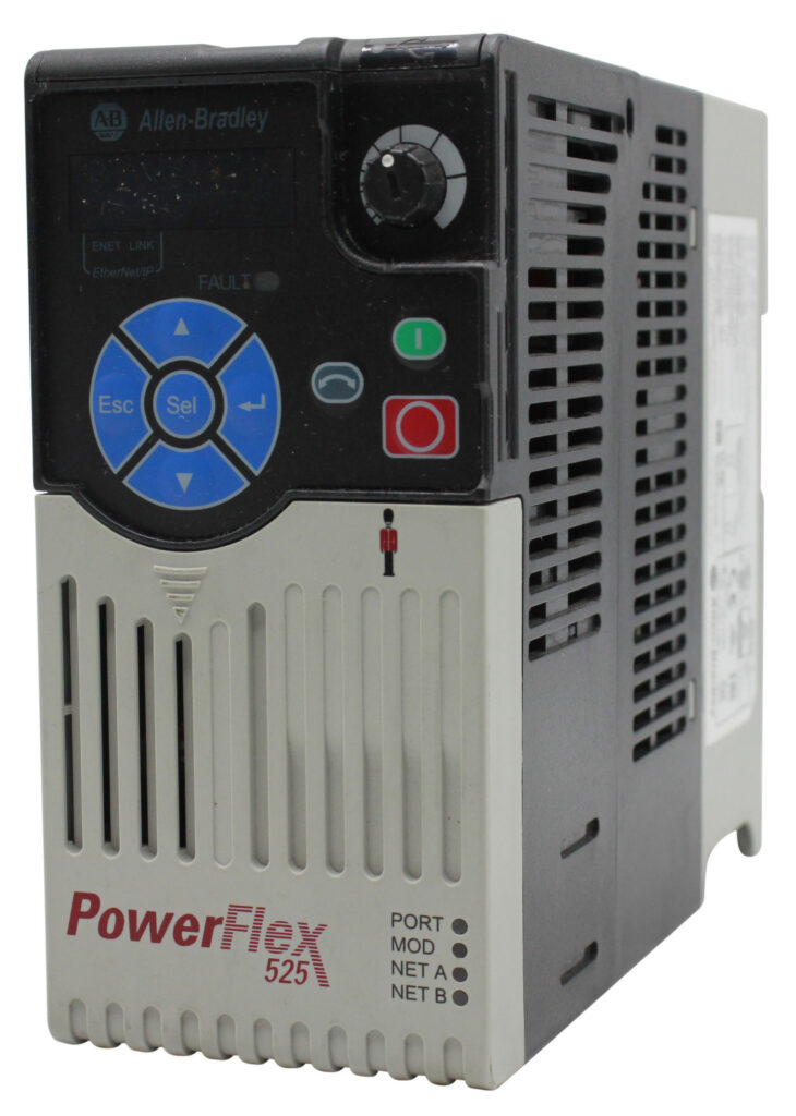
Lifting and hoisting operations pose significant overload risks, and a loss of load control can result in serious equipment damage or injury. Certain PowerFlex drives, including the PowerFlex 755 and 755T, offer TorqProve technology to help manage vertical loads securely. Before disengaging the mechanical motor brake, the drive verifies that the motor can develop sufficient torque to control the load. During stopping, the system also coordinates mechanical brake engagement before removing motor torque. On supported configurations, additional brake-proving functions can help detect brake slippage or an inability to hold the load. These features reduce the risk of uncontrolled load movement during lifting operations, although proper configuration, testing, and mechanical braking remain essential for safe operation.
Skip Frequencies and Resonance Overload Prevention
Mechanical resonance in operating machinery can cause localized vibration surges, increasing mechanical load resistance and motor current consumption at specific speeds. PowerFlex drives feature programmable skip frequency bands that avoid prolonged operation at vital resonant frequencies. System engineers input designated frequency ranges into the drive, directing the PowerFlex controller to swiftly accelerate through resonant speed bands without pausing. By avoiding operation at frequencies that induce vibrations, the drive minimizes mechanical stress on bearings and couplings, thereby preventing resonance-related current fluctuations that may cause unanticipated drive overload trips.
Final Thoughts
In conclusion, contemporary automated manufacturing necessitates motor drives that can handle abrupt mechanical stress to prevent line interruptions. PowerFlex drives maintain uninterrupted operation through a cohesive blend of active current foldback, smart thermal modeling, bus voltage regulation, and robust mechanical protection algorithms. By setting appropriate load ratings, torque limits, and fault-prevention thresholds, plant operators can improve equipment reliability and process availability. Implementing PowerFlex drives effectively helps prevent nuisance tripping, safeguards electrical infrastructure, so that unforeseen mechanical overloads are managed safely without hindering plant productivity.
For more on PowerFlex drives, check out our article on understanding DC bus voltage here! Also feel free to browse our online store, as we carry hundreds of different PowerFlex drives, from the entry level 40P to the feature packed 755. We also offer repair services for broken or malfunctioning drives so that we can get your operation running again. Need anything else? Contact our service team today and let us help you find what you’re looking for!
DO Supply Inc. makes no representations as to the completeness, validity, correctness, suitability, or accuracy of any information on this website and will not be liable for any delays, omissions, or errors in this information or any losses, injuries, or damages arising from its display or use. All the information on this website is provided on an "as-is" basis. It is the reader's responsibility to verify their own facts.