Common AC Drive Parameter Tuning Mistakes
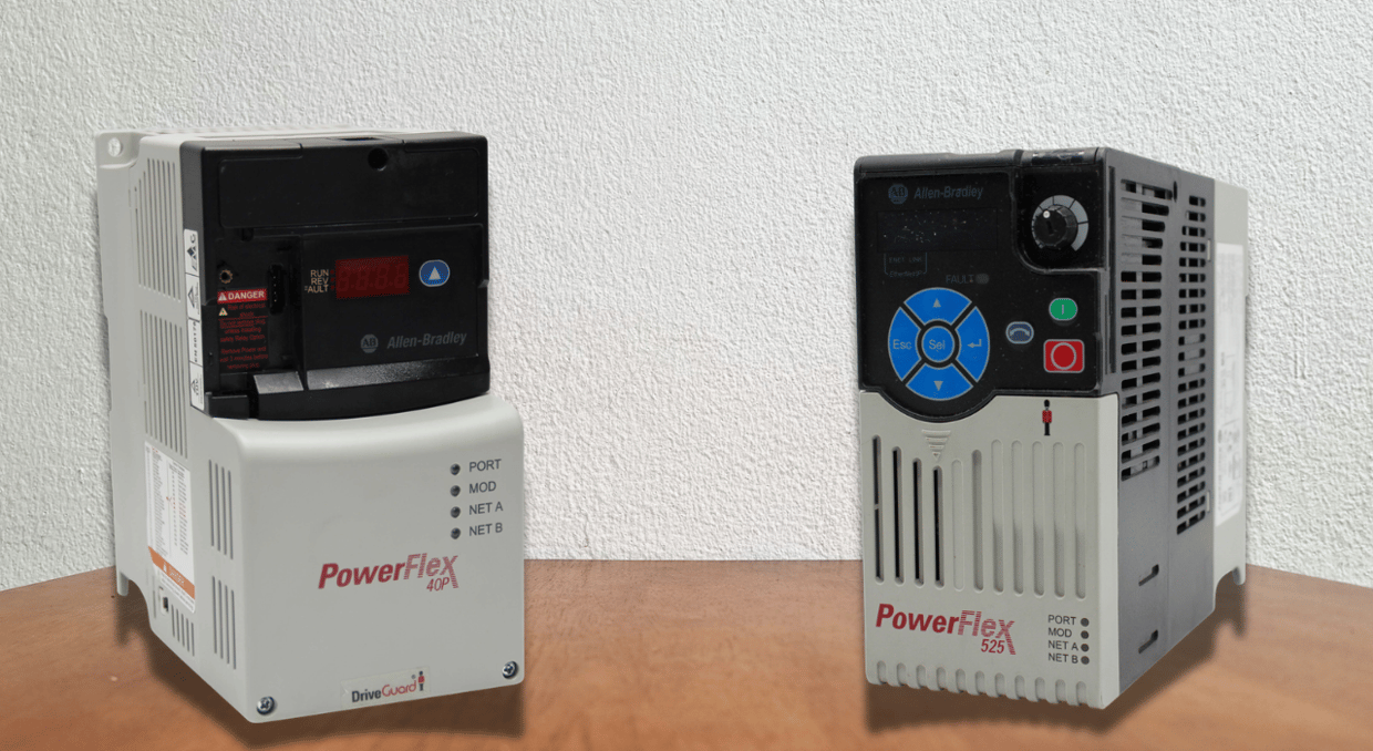
Alternating Current (AC) drives, commonly known as Variable Frequency Drives (VFDs), are critical components in modern industrial automation systems. By adjusting the frequency and voltage supplied to an AC motor, they precisely regulate its speed and torque. In industrial applications such as manufacturing, material handling, HVAC systems, machine tooling, water treatment, and chemical processing, AC drives enhance process control, improve operational flexibility, and significantly reduce energy consumption, especially in variable-flow fan and pump systems.
However, simply installing an AC drive does not guarantee optimal system performance. How effectively the connected AC motor maintains the required speed and responds to fluctuating loads depends entirely on proper drive selection, accurate parameter tuning, and proper AC drive commissioning. Incorrect parameter settings, misconfigured operating limits, or failure to execute the AC drive’s motor identification (autotuning) when required by the active control mode can cause poor motor speed regulation, unstable operation, intermittent faults, or nuisance trips, making troubleshooting during routine maintenance more difficult.
Immediate faults from incorrect parameter settings include DC bus overvoltage during braking or overcurrent alarms during motor startup. Other issues, such as mechanical oscillations, electrical noise, or excessive motor heating, develop over time. These issues can increase maintenance expenses or shorten the service life of the AC drive components, motor, and connected equipment.
Properly configuring an AC drive for reliable motor operation across the intended operating range involves much more than adjusting a few isolated parameters. It requires a thorough understanding of the motor characteristics, load dynamics, manufacturer’s commissioning procedures, and electrical installation requirements. This article explores common AC drive configuration mistakes, their underlying causes, and their effects on system performance. It also outlines practical measures to prevent or correct these mistakes during AC drive installation, commissioning, and maintenance.
Entering Incorrect Motor Nameplate Data
Entering incorrect motor nameplate data is a common mistake during AC drive commissioning and can compromise motor protection and drive performance. The AC drive’s internal processor uses motor parameters such as supply frequency, rated voltage, current, power, and nominal rotational speed in its motor-control calculations. In AC drive models with an electronic motor-overload protection feature, the drive’s motor thermal-protection algorithm utilizes relevant motor nameplate data and measured current to estimate motor heating. Some AC drives also support advanced vector-control algorithms and therefore require additional motor specifications.
Why the Mistake Occurs
Operators can sometimes enter the rated current of the AC drive rather than the full-load current of the motor. Additionally, some copy settings from older installations without first ensuring the replacement AC motor’s electrical characteristics are similar.
Incorrect parameter values can also be introduced by incorrect frequency selection, transcription errors, and confusion between kilowatts and horsepower. For instance, do not use 460 V, 60Hz settings on a motor meant for 400 V, 50Hz operation. Verify all motor parameters against the correct nameplate data and the manufacturer’s documentation.
Technical Consequences
Incorrect motor data can affect several drive functions:
- Motor Thermal Protection: Setting the motor’s rated current too high can reduce protection against motor overheating, while setting it too low can cause premature overload trips.
- Torque Production: Inputting incorrect motor nameplate parameters distorts the AC drive’s internal mathematical model. In sensorless vector control modes, incorrect drive configuration directly compromises dynamic speed responsiveness, torque accuracy, and low-speed stability.
- Current Monitoring and Protection: Incorrect motor rated-current settings miscalibrate the AC drive’s thermal-overload algorithm, causing it to miscalculate the motor’s loading percentage. This inevitably affects motor-overload protection and can trigger nuisance trips, even when the drive’s actual current measurements remain accurate.
The nature and severity of these effects depend on the particular motor parameter entered incorrectly, the selected motor control technique, and the AC drive’s control algorithms. Different incorrect nameplate values do not always produce the same operating issues.
How to Fix Them
Before enabling your AC drive, audit and cross-reference all the motor parameter settings against the provided nameplate data. Verify the motor’s supply frequency, rated voltage, current, power, and nominal rotational speed match the corresponding drive parameters. In addition, confirm that the delta or star (wye) winding connection is appropriate for the intended drive output voltage.
Verify that the available motor protection strategy suits your installation and configure the drive’s motor thermal-overload model accordingly. When a single AC drive operates multiple AC motors in parallel, its electronic thermal-overload algorithm cannot adequately protect individual motors operating under fluctuating or localized loads. In such multi-motor configurations, provide external thermal-overload protection for each motor in accordance with the applicable electrical codes and equipment manufacturer’s requirements.
Skipping Motor Autotuning and Identification
Motor autotuning is often overlooked during AC drive commissioning. Depending on the drive manufacturer, this procedure may be called motor identification, an identification run, or automatic motor adaptation. The procedure allows the AC drive to estimate or measure the motor’s electrical parameters required by the selected control algorithm. Depending on the drive and motor type, these motor characteristics—essential for accurate torque calculation and dynamic response—may include stator resistance, magnetizing inductance or current, and leakage inductance.
Why Motor Autotuning Matters
While the scalar Volts-Per-Hertz (V/Hz) control mode is sufficient for many conventional AC drive applications, it requires less detailed motor identification compared to advanced vector control methods. Sensorless Vector Control (SVC) relies heavily on an accurate internal motor model to precisely estimate quantities like motor speed and magnetic flux, and to regulate motor torque.
An incorrectly configured motor model can impair the AC drive’s ability to maintain steady motor control during rapid load variations or low-speed operation. For example, a conveyor may start normally when unloaded but draw excessive current or develop insufficient starting torque when loaded. In addition, an inaccurate motor model can also contribute to speed deviations in applications requiring precise velocity regulation, especially during transient load changes. When recommended or required by the drive manufacturer, autotuning improves the accuracy of the drive’s internal motor model, enhancing overall control performance.
Common Autotuning Mistakes
- Bypassing mandatory motor identification even when the manufacturer or the selected control mode requires it
- Initiating motor autotuning prior to entering the correct motor nameplate values
- Using a rotating motor autotuning procedure when safety requirements prohibit movement of the connected machinery
- Executing the tuning cycle while the load or motor is connected in a manner explicitly forbidden by the manufacturer
- Mistakenly assuming that all AC drives perform the same parameter measurements during autotuning
Recommended Corrective Actions
Select the motor-control mode well-suited for your AC drive application. Next, consult the drive manufacturer’s instructions to determine whether motor identification is recommended or required and whether a rotating or static autotuning procedure is appropriate for the motor and connected machinery.
Static motor identification generally applies electrical excitation without requiring the motor shaft to rotate. In contrast, rotating motor identification requires additional safety precautions and involves physically moving the motor shaft. These safety checks protect the equipment and personnel against hazards or unexpected machinery motion.
Before starting either procedure, verify the motor wiring, isolate the driven mechanism if needed, and ensure personnel are clear of any hazards. Adhere to all relevant machinery, electrical isolation, and lockout/tagout (LOTO) safety procedures. Then run the motor under controlled conditions at low speed after successful identification. Before restarting full production, confirm stable, precise speed control, torque, and current.
Note: Motor autotuning is not a universal command that is safe to execute under every operating condition; rather, it is a manufacturer-specific setup procedure.
Setting Acceleration and Deceleration Ramps Excessively Steep
An AC drive utilizes acceleration and deceleration ramps to control how fast the connected motor changes its commanded speed. These ramp settings affect mechanical stress, torque demand, and energy flow between the AC drive and connected motor. For instance, setting a deceleration ramp too fast can cause excessive regenerative energy from the motor to accumulate on the drive’s DC bus, leading to overvoltage faults. Conversely, a short acceleration ramp demands more torque and current than the AC drive and motor can reliably or safely deliver, which can result in an overcurrent trip or extended acceleration.
Understanding Acceleration-Related Overcurrent
A motor generates torque to overcome friction and accelerate the combined inertia of the connected equipment and the motor. The requested rate of speed change is directly proportional to the acceleration torque required by a given motor-load system inertia. For example, a small pump may require a shorter acceleration period than a high-inertia load such as a heavily loaded conveyor system or a large centrifuge.
When an AC drive attempts to accelerate a high-inertia load too rapidly (due to an excessively short acceleration ramp setting), the high transient torque demand causes the motor current to exceed the drive’s configured current limit. Depending on its settings, the drive’s internal control strategy can trigger a safeguard to protect its power electronics—typically resulting in an immediate overcurrent trip or a prolonged acceleration ramp.
Understanding Deceleration-Related Overvoltage
During controlled deceleration, energy stored in the rotating motor and applied load can continually drive the motor. This causes the motor to act like an induction generator, returning electrical energy to the drive’s DC bus. If the regenerated energy exceeds the drive system’s capacity to absorb it, dissipate it through the braking system, or return it to the power supply through a regenerative unit, the DC bus voltage rises. High-inertia loads are particularly susceptible to DC bus overvoltage trips when the deceleration ramp time is too short.
How to Fix Overvoltage and Overcurrent Conditions
- If the AC drive repeatedly reaches its configured current limit during startup, evaluate the load’s static torque and rotational inertia requirements and increase the acceleration ramp time where the application’s process cycle permits. Increase the acceleration ramp time gradually to reduce the transient current demand on the AC drive.
- If DC bus overvoltage trips occur during stopping, increase the deceleration ramp time, where permitted by the application
- If the drive-motor system requires rapid or frequent stopping, add a manufacturer-approved braking chopper and a regenerative unit or braking resistor
- Ensure that the included braking components match the system’s thermal requirements and duty cycle
- Verify the selected acceleration and deceleration ramp settings under representative load conditions while monitoring braking-component temperatures, DC bus voltage, and motor current
Setting the Carrier Frequency Too High
Switching frequency (carrier frequency) determines how an AC drive’s power transistors switch to synthesize the voltage waveform of the connected motor. It is entirely unrelated to the fundamental output frequency that controls how fast the motor operates.
In some industrial applications, a high carrier frequency improves current waveform quality or reduces audible motor noise. Nevertheless, when increased under certain installation conditions, it increases thermal stress and motor insulation stress.
Why an Unnecessarily High Carrier Frequency Becomes a Problem
During each switching state, AC drive power semiconductors dissipate energy as heat. As a result, total switching losses and heat generation scale proportionally as switching frequency increases. The exact thermal impact depends on the active modulation method, the continuous output current magnitude, and the drive’s internal hardware design. An excessively high switching frequency when the AC drive is under a heavy load spikes internal temperatures. Under these conditions, the AC drive may automatically reduce its carrier frequency, limit output current, or trip on overtemperature, depending on its design and settings. Also, to keep the AC drive system from overheating during higher switching frequencies, some manufacturers explicitly outline specific output-current derating requirements.
Potential Effects of Excessively High Switching Frequency
- A forced drop in thermal derating or drive overheating under a sustained load operation
- Reduced continuous output-current capacity relative to the drive’s nominal rating due to application of carrier-frequency derating curves
- Interference that disrupts nearby control instruments or increased electrical noise
- A high-pitched, constant motor hum despite otherwise satisfactory operation
- Accelerated wear and tear on power components, especially when operated beyond their safe thermal limits
Recommended Corrective Action
Begin with the manufacturer-recommended carrier frequency setting. If the application demands a distinct performance boost or benefits from reduced audible noise, you can raise it. A lower frequency is preferable in installations with restricted ventilation or heavily loaded equipment, if the application can tolerate the extra motor noise.
If electrical interference occurs, assess the entire motor-drive system electromagnetic compatibility (EMC), including shielding, EMC filtering, grounding, bonding, and cable routing. Correct any deficiencies in accordance with the drive manufacturer’s specifications and compliance guidelines. Lowering the switching frequency alone may not resolve the electrical interference.
For permitted motor-cable lengths and current derating tables, technicians should first check the AC drive’s technical documentation. An adjustment to the carrier frequency should not override other manufacturer’s engineering specifications and thermal limits
Neglecting Minimum and Maximum Operating Speed Limits
The permitted operating speed range of an AC drive-controlled AC motor is established by the minimum and maximum frequency or speed settings. Incorrectly configuring these limits can affect available torque, energy consumption, lubrication, and motor cooling. The AC drive should not operate beyond its unrestricted frequency range before identifying whether the driven machine or the motor can safely operate under those conditions. Set the AC drive’s operating limits according to the motor and equipment manufacturers’ specifications and your application requirements.
Problems Associated with Low-Speed Operation
A shaft-mounted fan is deployed in multiple standard induction motors for cooling. The fan’s cooling capacity decreases as motor speed decreases. A motor running repeatedly at low speed overheats because it produces substantial torque even when its current is below the nominal rated value.
Certain industrial applications require minimum process requirements. Minimum flow rate settings in pumps prevent unstable operation and maintain lubrication. It is compulsory to observe minimum-speed restrictions in some mechanical systems and gearboxes. These limitations vary by application and motor construction. Separately cooled motors can support specific low-speed operating settings.
Problems Associated with High-Speed Operation
Depending on the motor design and the AC drive model, high-speed operation above the motor’s base frequency exposes the motor to a field-weakening region. When speed is beyond the base operating point, available torque decreases. Increasing the speed limits can also exceed pump, gearbox, or bearing physical limits. Excessive operating speed can also substantially increase power demand in centrifugal pumps and industrial fans.
Recommended Next Steps
Set the allowable operating frequency range based on process requirements and the motor and driven equipment manufacturer’s specifications. Evaluate whether a suitably rated motor or independent motor cooling is necessary where low-speed operations require substantial torque. Ensure that lubrication requirements and gearbox limits are satisfied. Maximum and minimum frequency settings should reflect the verified operating limits of the motor and driven equipment.
Sometimes your drive faults aren’t caused by your drive at all. Sometimes the drive may need repair instead. If so, we at DO Supply can repair your drive and get it running strong again, backed by our two-year warranty. We also carry drive accessories, motors to be powered by it, or PLCs to help complete your automated system. Inquire today and see what we can DO for you!
DO Supply Inc. makes no representations as to the completeness, validity, correctness, suitability, or accuracy of any information on this website and will not be liable for any delays, omissions, or errors in this information or any losses, injuries, or damages arising from its display or use. All the information on this website is provided on an "as-is" basis. It is the reader's responsibility to verify their own facts.