Servo and Stepper Motors: From Steamboats to Robots
Motors. They turn the wheels of an electric car, move products seamlessly along a conveyor belt, launch a 3D printer’s head into action to craft precise plastic models, and even create the tactile feedback you feel in a game controller. Whether we’re talking about transportation, manufacturing, or entertainment, motors are everywhere. In fact, there are at least a dozen different types to choose from, each tailored to meet a specific need, whether it’s precision, speed, torque, or efficiency. Yet, with so many choices, getting lost in the technicalities is easy. This article will focus on two parts: the stepper motor and the servo motor.
The Run Down on Stepper Motors
The stepper motor was the answer to the growing need for reliable and repeatable motion control. Developed in the 1920s and gaining widespread adoption by the 1950s, these motors quickly became indispensable across a variety of industries. From textile factories ensuring precise fabric weaving to military-grade avionics systems where precision could mean the difference between success and failure, stepper motors found their niche.
The name “stepper” comes from how these motors operate: moving incrementally in fixed angles, known as steps. Each step represents a small, exact movement, allowing for highly controlled and repeatable positioning without needing complex feedback systems. Its this repeatability and precision that opened the doors for modern day CNC machines and even early computer printers. Today, they have become extremely accessible and can be noticed turning away in 3D printers, laser cutters, and even camera systems.
Unlike servo motors, a notable advantage of stepper motors is their open-loop control system. Since the motor’s movements are determined by the input signal and each step is predictable, there’s no need for complex sensor feedback loops to ensure accuracy. This reduces both the cost and complexity of control systems, which was a significant benefit to industries trying to automate processes at scale.
In addition, stepper motors are known for their ability to hold their position when stationary, unlike other types of motors that need continuous power to maintain position. This made them ideal for applications where maintaining a fixed position is critical, such as holding a camera or laser steady during a scanning operation.
Where the Servo Motors Step In
Servo motors have quite a history, dating back to the early 19th century when the need for precise control systems began to take shape. These motors were designed to follow commands from a control system with great accuracy. Interestingly, the name “servo” comes from the Latin word servus, meaning “servant”. The foundation for servo motor technology started with the development of feedback control systems. One of the most notable pioneers in this area was James Watt—yes, the same man for whom the SI unit “Watt” is named.
Watt applied feedback control concepts in his steam engines to regulate speed and maintain stability, laying the groundwork for the first servo-like systems. His centrifugal governor, for example, was an early form of mechanical feedback control, automatically adjusting the flow of steam to stabilize engine speed. While not an electric servo as we know them today, it effectively controlled power output and ensured smooth, reliable operation.
In the late 19th and early 20th centuries, hydraulic servo systems were developed, especially in large-scale applications. These used pressurized fluids to control mechanical movement. Hydraulic systems were particularly important in aviation and naval applications, where high power and precise control were needed to move heavy equipment like aircraft control surfaces or ship rudders. Hydraulics provided the necessary force, while a feedback mechanism (often mechanical) ensured accurate control.
Transition to Electrical Servo Motors
The transition from mechanical and hydraulic servos to electrical servo motors began in the early 20th century as electrical technology advanced. The first electrical servos were either AC or DC motors with analog feedback systems. These systems used electrical signals to regulate movement, allowing for more precise control than mechanical or hydraulic counterparts.
- DC Servo Motors: Early electrical servo motors often used direct current because DC motors provided smoother and more controllable torque, which was essential for precise applications like radio systems, aircraft, and early automation machinery. In these systems, a potentiometer (a type of position sensor/resistor) or an analog tachometer was used as feedback to adjust the motor’s position based on the input signal.
- AC Servo Motors: Later, AC servo motors were developed for higher-power applications. These were often paired with synchronous or induction motors, allowing for better industrial performance.
The evolution toward electronic control systems during the mid-20th century brought about the use of electronic feedback loops and encoders, which allowed servo motors to achieve even greater precision and responsiveness.
Stepping into the Modern Age
Now, when we transition from steamboats to automated factories, a lot has changed when it comes to motor design. While the core principles haven’t changed, modern advancements have significantly improved their reliability, performance, and versatility. For stepper motors, there has been quite a list of refinements done; these include:
Increased Torque and Speed
The transition from ferrite magnets to neodymium magnets was a significant leap in generational performance for these motors, boasting increased torque gains by up to 40%. This allows the motors to turn faster, hold their positions better, and not have to compromise on precision for power.
Enhanced Resolution
As mentioned before, stepper motors use an open-loop configuration. That means that each pulse of current delivered by the drive equals one step of the motor, which is a predetermined angle of rotation. This, however, makes these systems operate under the assumption that the motor accurately executes each command step, as there is no feedback mechanism to verify its actual position. Stepper motors may also miss steps if the load is too great or the acceleration is too fast, leading to positioning errors. Resonance also plays a role, as the lack of a feedback system means there is no compensation at higher speeds.
However, technology has improved greatly over the years. Microstepping has been introduced, which divides each full step into smaller increments by varying the current in the motor’s windings. This allows for smoother motion and a higher resolution. For example, a 1.8-degree stepper motor can reach resolutions as fine as 0.0072 degrees with 256 microsteps per step. New drivers also boost energy efficiency and reduce heat generation.
Better Housings and Thermal Management
While casings aren’t as cool as new tech, they are still a vital part of the motor’s performance. The transition to aluminum alloys, like 6061-T6 and 7075-T6, improved tensile strength for durability, better thermal conductivity for heat dissipation, and decreased weight by up to 30%. Some motors even use magnesium alloys to save even more weight. Those stepper motors are typically found in aerospace applications. Stainless steel is used for harsher or corrosive environments, such as food processing plants or marine applications. While they are heavier, they offer superior durability and corrosive resistance.
Along with better materials, integrated heat sinks were introduced. These are the fins typically found on the motor housings. They allow for more surface area to transfer the motor’s heat into the cooler ambient air. Integrated heat sinks allow heat pipes and vapor chambers to transfer heat using the evaporation and condensation of a fluid within a sealed system. This allows for excellent heat transfer while keeping a small form factor.
Modular housing designs have also made it easier to work on these motors or configure them exactly to your needs. A welcomed feature that technicians absolutely adore.
Modern Servo Motors
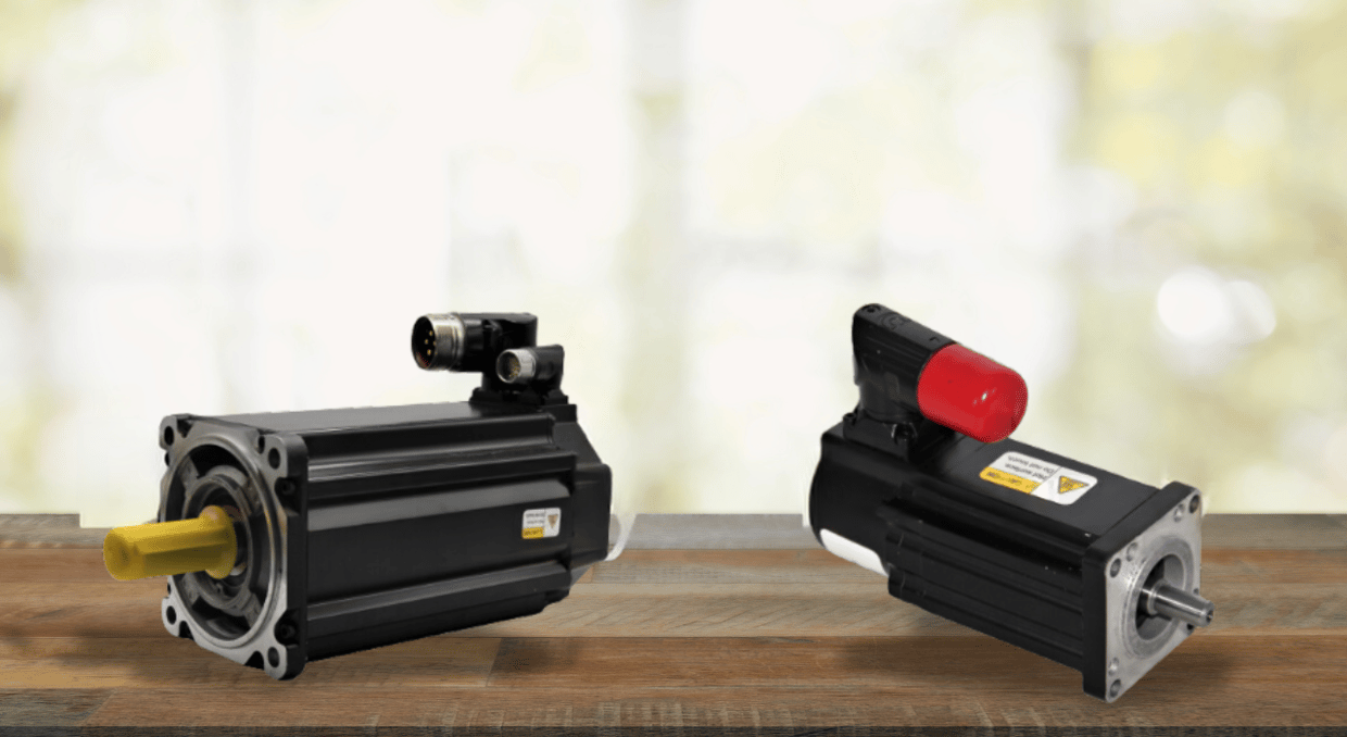
Stepper motors aren’t the only motor that has significantly improved over the years. With the introduction of direct drive servos, linear servos, better manufacturing processes, cost-reducing measures, and general design, it’s no wonder these motors are extremely prevalent in industrial factories today. While all of those new specs sound fancy, we assure you that they’re about to get better. For a more tangible benchmark, we will compare the older Allen-Bradley Bulletin 1326 servo motors, which were prevalent in the late 1980s and early 1990s.
Torque and Speed Enhancements
Just like stepper motors, modern servo motors now use Neodymium magnets for increased torque numbers. For example, the Kinetix VPL line has up to 163 Nm of torque, whereas the Bulletin 1326 had up to 20 Nm of torque in a similar-sized frame. Speed has also gotten a significant boost, as the older motors maintained a maximum speed of around 3,000 RPM, whereas the modern servos exceeded 6,000 RPM with maintained torque output. The performance gain is as significant as the numbers make it seem.
Feedback System Reworks
The feedback system is the heart and soul of a servo motor’s precision and responsiveness. It acts as the communication bridge between the motor and the controller, ensuring that the motor’s actual position, speed, and torque align with the desired commands. As mentioned, these motors run on a closed-loop control system, meaning they constantly monitor and adjust their performance based on feedback. Here’s how:
- Command Signal: The controller sends a command to the servo motor, specifying the desired position, speed, or torque.
- Movement Initiation: The motor begins to move according to the command.
- Real-Time Monitoring: As the motor moves, the feedback device, such as an encoder or resolver, measures the motor’s actual position or speed.
- Feedback Signal: This real-time data is sent back to the controller.
- Error Detection: The controller compares the actual motor status with the desired command to identify any discrepancies, known as errors.
- Adjustment: If there’s a difference, the controller adjusts the motor’s input signals to correct the error, bringing the motor’s performance in line with the desired outcome.
The feedback system depends on what technology lies within the motor. Some of these are:
- Incremental Encoders: Provide pulses corresponding to movement with resolutions exceeding 10,000 pulses per revolution and quadrature encoding for direction detection and increased precision.
- Absolute Encoders: Offer unique digital codes for each shaft position. These allow for multi-turn capability without external power and increased resolutions from 12-bit to 24-bit and higher. 24-bit encoders can distinguish over 16 million positions per revolution for extremely precise control.
- Resolvers: Use electromagnetic coupling to determine position.
- Hall Effect Sensors: Detect magnetic fields to determine rotor position.
- Magnetic Encoders: Utilize magnetic fields for position sensing.
- Optical Encoders: These use light sources and photodetectors to read patterns on a disk.
- Capacitive Encoders: These rely on changes in capacitance to determine position.
This means that the new servo motors offer superior precision, improved responsiveness, simplified integration, and even enhanced diagnostics.
Build Quality and Construction
Beyond torque and speed, modern servo motors’ build quality and construction have seen remarkable advancements. These improvements significantly enhance their reliability, efficiency, and longevity in demanding industrial environments.
Modern servo motors, like the Allen-Bradley Kinetix series, are built using high-strength materials that offer superior performance compared to older models like the Bulletin 1326. The transition to advanced aluminum alloys such as 6061-T6 and 7075-T6 has reduced motor weight by up to 30%. This not only makes installation and maintenance easier but also improves thermal conductivity for better heat dissipation.
Speaking of heat, improved thermal management is also important for modern servo motors. Integrated heat sinks, incorporated directly into the motor housing, are now a common design element. These heat sinks increase the surface area for heat exchange, allowing the motor to run cooler under heavy loads. This is a significant upgrade from older models, which often relied solely on the motor’s mass for heat absorption and lacked efficient cooling mechanisms.
Precision manufacturing techniques have further enhanced build quality. Automated CNC winding machines ensure consistent and precise coil windings, reducing electrical losses and increasing overall efficiency. This level of precision wasn’t achievable with the manual winding processes that were common in the past.
Environmental resilience has also improved. Modern servo motors feature higher Ingress Protection (IP) ratings, like IP66 and above, offering better dust and water ingress resistance. Enhanced sealing techniques protect internal components from contaminants, extending the motor’s operational life and reliability.
Final Thoughts
There is a lot more that goes on underneath those fancy 6061-T6 chassis than meets the eye. Each decade brings new innovations that keep our conveyor belts moving better and robot arms drawing less power. Now, the next time you see a 3D printer whirring away or even the wheels moving on an electric car, you can understand what is happening to make those machines move.
We at Do Supply carry an extensive range of Allen-Bradley motors, from food-grade to heavy-duty, all backed by our 2 year Do Supply warranty. Visit us at DoSupply.com to find the perfect drive for your applications. Though a motor is much more useful with a drive paired with it, thats why we came up with this guide on choosing the right drive between Mitsubishi and Allen-Bradley offerings.
DO Supply Inc. makes no representations as to the completeness, validity, correctness, suitability, or accuracy of any information on this website and will not be liable for any delays, omissions, or errors in this information or any losses, injuries, or damages arising from its display or use. All the information on this website is provided on an "as-is" basis. It is the reader's responsibility to verify their own facts.