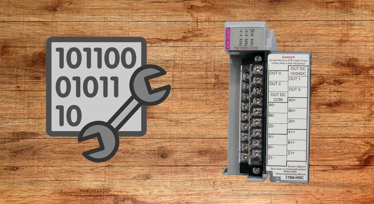
Troubleshooting Analog Input vs Digital Input Errors in PLC Systems
Programmable logic controllers process two fundamental categories of field signals: analog inputs and digital inputs. Each signal type has distinct electrical characteristics, wiring requirements, module architecture, and failure behavior. When faults occur on either input type, the diagnostic approach differs significantly. Engineers and technicians who understand the behavior of analog vs. digital input systems are better positioned to identify faults quickly and implement corrections. This article provides a structured technical framework for troubleshooting analog input vs digital input errors in PLC systems.
Analog Input vs Digital Input Signals
A digital input signal is binary in nature. The field device, such as a pushbutton, proximity sensor, limit switch, or relay contact, produces either a voltage-present or voltage-absent condition. The PLC digital input module interprets this as a logic-1 or logic-0 state. Most digital input modules operate at 24VDC. The module contains optical isolation circuitry that separates the field voltage from the controller backplane, and the input state is stored as a single bit in the controller’s input image table.
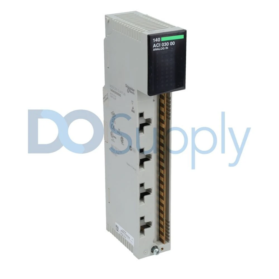
An analog input signal carries continuous process-variable data encoded as a current signal (4–20 mA), a voltage signal (0–10V, ±10V), or a resistance-based signal from a thermocouple or RTD. The analog input module contains an analog-to-digital converter that samples the incoming signal and converts it to a raw integer count stored in a 16-bit or 32-bit data register. Resolution is typically 12-bit, 14-bit, or 16-bit, depending on the module specification.
Troubleshooting Digital Input Errors
Signal State Errors
The most common digital input fault is an incorrect input state: the input reads logic-1 when the field device is off or logic-0 when it is energized. Begin diagnosis at the module status LEDs. If the LED state matches the expected field condition but the controller data table shows a different value, the fault lies in the module, backplane communication, or controller configuration. If the LED does not match, the fault is in the field wiring or the field device.
Voltage measurement at the input terminals is the primary verification method. For a 24VDC module, a nominal ON state should produce 18–26VDC at the input terminals relative to the module common. A reading below the minimum threshold, typically 11VDC, will not reliably trigger the input. Zero volts with the device commanded on indicates an open circuit, a failed output on the sourcing device, or a blown fuse.
Contact Bounce and Filter Configuration
Mechanical contacts produce signal bounce during switching transitions. PLC digital input modules include configurable input filter circuitry with filter times typically ranging from 0ms to 32ms. If the filter time is set too short for the field device switching characteristics, the controller may register multiple input transitions from a single actuation, causing erratic logic behavior. Increase the filter time incrementally and monitor input behavior until transitions stabilize.
Sinking vs Sourcing Wiring Errors
Wiring a sinking device to a sourcing module, or vice versa, will either prevent the input from activating or cause it to appear permanently energized. Verify the module wiring diagram against the installed wiring before assuming a module or sensor fault. This is a common commissioning error that can appear identical to a hardware failure without careful verification of wiring.
Optical Isolation Failures
Optocoupler degradation produces an intermittent or failed input response that cannot be explained by field wiring conditions. A degraded optocoupler may respond unreliably at normal input voltages but activate correctly at elevated voltages. Diagnosis requires substituting the module with a known-good spare and observing whether the fault follows the module or remains in the field circuit.
Troubleshooting Analog Input Errors
Analog input fault diagnosis is more complex because the signal carries quantitative process data rather than a binary state. Errors can be absolute, no signal present, or graduated, where the signal is present but inaccurate, noisy, or drifting.
Open Circuit and Short Circuit Detection
Most analog input modules implement open-circuit and short-circuit detection for 4–20 mA current-loop signals. An open circuit drops the loop current to zero, triggering an underrange condition. The module sets an underrange status bit and drives the raw count to the minimum scale value. A short circuit raises the current above 20mA, triggering an overrange condition.
When an underrange fault appears, measure the actual loop current by placing a multimeter in series with the loop. Zero milliamps with the transmitter powered confirms an open circuit. Isolate the fault by disconnecting the field wiring at the module terminals, then measure continuity back to the transmitter. Inspect terminal blocks, cable splices, and junction boxes for open connections or corroded terminals.
Signal Scaling and Engineering Unit Errors
Scaling errors produce process variable readings that are offset, inverted, or nonlinear relative to the actual measured value. These errors originate in module configuration parameters, input range selection, scaling limits, and engineering unit conversion factors, rather than in field hardware.
Verify that the configured input range matches the transmitter output range. A transmitter with a 4–20mA output connected to a module channel configured for 0–10V input produces meaningless data. Apply a known reference signal using a calibrated loop calibrator at the module terminals and compare the resulting scaled value against the expected output to confirm whether the error is in the configuration or in the field transmitter calibration.
Noise and Signal Interference
Analog input signal noise causes fluctuations in values that go beyond those caused by changes in the process variable itself. Noise sources include VFD switching transients, high-voltage cable routing near signal cables, and ground loops from improper shield termination.
Measure noise by monitoring the raw analog count at a high scan rate, or by connecting an oscilloscope across the input terminals. High-frequency noise above 100Hz typically originates from VFDs or switching power supplies. Noise in the 50–60Hz range indicates power line interference, often caused by ground loops.
Ground loops occur when a cable shield is grounded at both ends, creating a current path that injects noise into the signal. Ground the shield at the control panel end only, leaving the field end floating. For persistent noise, implement a first-order lag filter or a moving average in the controller program to reduce its impact on the control logic.
Thermocouple and RTD Input Errors
Thermocouple open-circuit faults are detected by the module’s burnout detection circuit, which drives the channel to full-scale upscale or downscale depending on the configuration. Verify that the burnout direction matches the application’s fail-safe requirement.
Thermocouple polarity reversal produces a reading that decreases with increasing temperature. Verify that positive and negative leads are connected to the correct module terminals. The extension wire must match the thermocouple type and be installed with the correct polarity; a mismatched extension wire introduces measurement error at the dissimilar metal junction.
RTD wiring configuration errors are common in three-wire and four-wire applications. A three-wire RTD connected as a two-wire input loses lead resistance compensation, introducing a positive offset proportional to lead resistance. Verify that the module is configured for the correct RTD wiring mode and that all leads are connected to designated terminals.
Module-Level Hardware Faults
Backplane Communication Errors
Backplane communication faults produce module status errors in the controller fault table, causing affected channels to report fault values rather than valid field data. Remove and reseat the module to confirm proper backplane contact. Inspect the module edge connector and chassis slot for physical damage or contamination. If the fault persists, substitute the module into a different chassis slot to determine whether the fault follows the module or remains in the original slot.
Firmware and Configuration Compatibility
Input module firmware must be compatible with the controller firmware version in use. A module firmware version newer than what the controller supports may produce configuration faults or erratic channel behavior. Verify firmware compatibility in the manufacturer’s release notes and update as required.
Software Diagnostic Methods
Online monitoring in the PLC programming software provides real-time visibility into analog input vs digital input channel data, module status bits, and fault registers. For analog inputs, the channel status word contains individual bits indicating underrange, overrange, open wire, and out-of-range conditions. Monitoring these bits directly accelerates fault identification without requiring physical measurement at the module terminals.
Trend logging of analog input values over time reveals patterns, periodic noise spikes correlated with VFD switching, slow drift indicating transmitter calibration degradation, or step changes indicating intermittent wiring connections.
For digital inputs, force functions in the programming software allow individual input bits to be set to a known state for logic testing, independent of the field signal. This isolates whether a control problem originates in the input signal or in the ladder logic processing it. Force functions must be removed immediately after diagnostic use.
Final Thoughts
In conclusion, troubleshooting analog input vs. digital input errors in PLC systems requires a structured approach that begins at the field device, progresses through wiring verification and module hardware diagnostics, and concludes with configuration and software-level analysis. Digital input faults are generally binary and can be traced through voltage measurements and LED status observations. Analog input faults range from hard open-circuit conditions to subtle noise and calibration errors that require quantitative signal analysis. Applying a consistent troubleshooting methodology to analog input vs digital input errors reduces fault resolution time and ensures corrective actions target the actual failure mechanism rather than its surface symptoms.
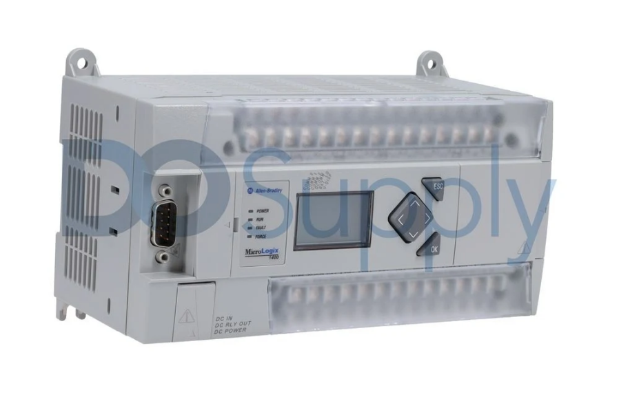
At DO Supply, we take reliability seriously. That’s why all of our products are tested and are backed by our two-year warranty. On top of that, we extend our services to repairs and replacements if your PLCs and other industrial equipment are having faults. If this sounds like something you need, then give us a call or send us an email today, or check out our other maintenance blogs, like this one, going over maintenance for the MicroLogix series PLCs.
DO Supply Inc. makes no representations as to the completeness, validity, correctness, suitability, or accuracy of any information on this website and will not be liable for any delays, omissions, or errors in this information or any losses, injuries, or damages arising from its display or use. All the information on this website is provided on an "as-is" basis. It is the reader's responsibility to verify their own facts.