Allen Bradley Troubleshooting: Common Drive and PLC Issues Explained
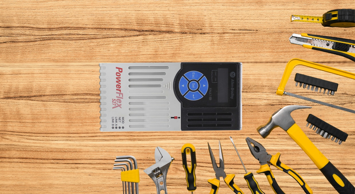
Allen-Bradley is one of the most trusted names in industrial automation worldwide. From manufacturing plants, Building Management Solutions, and oil refineries to water treatment facilities and food processing lines, Allen-Bradley drives and PLCs (Programmable Logic Controllers) power critical infrastructure across virtually every sector of modern industry.
Yet even the most reliable industrial systems encounter faults, trip events, and communication errors. When an Allen-Bradley drive trips unexpectedly or a PLC fails to execute logic correctly, production lines can halt within seconds, resulting in lost output and costly downtime. The ability to diagnose and resolve these issues quickly is not just a technical skill; it is an operational necessity.
This guide walks through the most common Allen-Bradley drive (focusing on the 525, 700, and 750-series) and PLC (CompactLogix and ControlLogix) faults encountered in real-world environments. For each issue, you will find an explanation of the underlying cause, the symptoms to look for, and proven corrective steps. Whether you are an automation engineer, maintenance technician, or systems integrator, this resource will help you restore operations faster and more confidently.
Allen-Bradley Fault Reporting System
Allen-Bradley systems use a structured, hierarchical fault reporting system. PowerFlex drives surface fault codes on the HIM display and stores them in the fault queue, accessible via Parameters 238 (Fault 1 Code) through 247 (Fault 10 Code). Each stored entry includes the fault code, the elapsed runtime at the time of fault occurrence, and the DC bus voltage at that moment. This three-point snapshot is critical for distinguishing nuisance trips from hard faults.
On the PLC side, ControlLogix and CompactLogix controllers classify faults as Major (execution halts, status LED flashes red) or Minor (logged, execution continues). Major faults carry a Type (1–4) and Code. Type 1 is program/task-related, Type 2 is I/O module-related, Type 3 is motion-related, and Type 4 indicates a hardware failure. Always capture Type, Code, and the Program/Routine name from the log before clearing.
Allen Bradley Drive Troubleshooting
Overcurrent Faults (F12)
Overcurrent faults trigger when instantaneous output current exceeds 200–250% of the drive’s rated current, or when sustained output current exceeds the programmed overload threshold. On PowerFlex 525 and 755 drives, Parameters 27 (Current Limit) and 28 (Motor NP FLA) directly govern the trip threshold; an incorrect motor nameplate entry is a frequently overlooked cause of nuisance overcurrent trips.
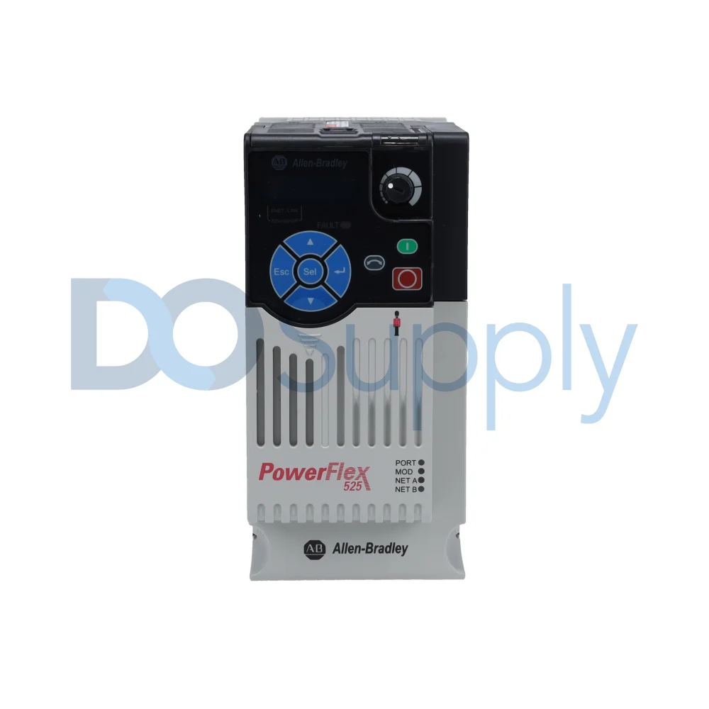
Diagnostic isolation follows a structured sequence. Disconnect the motor at output terminals T1/T2/T3 and command a run. If F4 persists with no motor connected, an internal IGBT or gate driver fault is confirmed; the drive requires replacement. If the fault clears, perform a phase-to-phase resistance check using a low-resistance ohmmeter; an imbalance exceeding 5% between phases indicates developing turn-to-turn shorts. Follow with a 500V DC megohm test; insulation resistance below 1 MΩ phase-to-ground confirms insulation breakdown. If the motor and cabling test within specification, verify Parameter 25 (Accel Time 1). Aggressive ramps on high-inertia loads generate current spikes during acceleration that exceed drive ratings, increasing Accel Time 1 from the default 10 seconds to 20–30 seconds, which frequently eliminates the fault without any hardware change.
Overvoltage Faults (F3, F5)
Overvoltage faults are generated when the DC bus voltage exceeds approximately 810V DC on 480V-class drives. The bus voltage logged in Parameter 243 at the time of fault occurrence indicates whether the fault is regenerative (the bus rises during deceleration) or supply-side (the bus is elevated at rest).
Regenerative overvoltage during deceleration is resolved by increasing Parameter 26 (Decel Time 1). Where deceleration time extension is operationally unacceptable, a dynamic braking resistor is required. The DB resistor must be sized based on load inertia (WK²), speed, and stopping frequency; undersized resistors overheat and fail. Enable the DB function via Parameter 161 (DB Resistor Select) on PowerFlex 525/755 drives and verify the resistor value falls within the drive’s specified minimum DB resistance to prevent IGBT damage. Supply-side overvoltage with an elevated bus at rest points to utility line disturbances, a 3% line reactor ahead of the drive attenuates voltage transients and protects the rectifier bridge.
Ground Fault (F13)
F13 trips when the leakage current to ground exceeds approximately 50% of the drive-rated current. Isolation begins by disconnecting output cables at T1/T2/T3. If F13 clears, megohm-test all output cables conductor-to-ground, resistance below 1 MΩ confirms cable insulation failure, typically at conduit entry points where mechanical abrasion occurs. If the cables test good, reconnect and disconnect at the motor terminal box, then megohm-test each motor terminal to the motor frame. Motors with carbon tracking in the terminal box can pass a cold megohm test, but fail under operating temperature. Thermal cycling exacerbates insulation degradation on aged windings. If both motor and cables test satisfactorily, investigate long cable runs exceeding 100 feet, where high cable capacitance generates displacement current sufficient to trigger the ground fault circuit. Output reactors or dV/dt filters prevent ground-fault nuisance trips in long-cable installations.
Overtemperature Faults
On PowerFlex drives, overtemperature faults vary by family. On the PowerFlex 525, F008 Heatsink OvrTmp indicates that the heatsink or power module temperature has exceeded a predefined value. In contrast, F009 CC OvrTmp indicates that the control module temperature has exceeded a predefined value. These conditions can be monitored on the 525 through b027 [Drive Temp] and b028 [Control Temp]. On PowerFlex 750-Series drives, heatsink and transistor overtemperature conditions are also tracked in the drive diagnostics and fault status structure.
Primary causes include inadequate airflow, blocked or dirty heatsink fins, elevated ambient temperature, failed cooling fans, and switching losses associated with PWM frequency settings. On the PowerFlex 525, PWM frequency is set through A440 [PWM Frequency]. On the PowerFlex 700, PWM frequency is set through parameter 151 [PWM Frequency]. If motor noise is not a concern, reducing PWM frequency may help reduce thermal stress, but the exact temperature change depends on the application and should not be stated as a fixed number without a source. Inspect fans for failure, inspect the heatsink and enclosure for dirt or airflow restriction, and verify that the surrounding ambient temperature remains within the drive’s rated range.
Allen Bradley PLC Troubleshooting
EtherNet/IP Communication Faults
Physical-layer and network communication issues are a common cause of Ethernet/IP faults. In Logix systems, communication capacity depends in part on the number of active CIP connections and the selected Requested Packet Interval (RPI), so aggressive network update rates can reduce the number of devices a controller can practically support. When communication faults occur, start with the physical network: inspect Ethernet cabling and switch health, verify power and link status at the affected devices, and confirm that the network is operating within the controller’s supported connection limits.
Power Supply and Backplane Faults
On the ControlLogix chassis, the 1756-Pxxx power supply provides 1.2V, 3.3V, 5.1V, and 24V DC power to the backplane. If a power issue is suspected, verify that the chassis load is within the output rating of the installed supply. Calculate total backplane current draw by summing the requirements of the installed modules and comparing them against the supply’s rated output. An overloaded 1756 chassis can exceed its supply capacity as additional modules are added over time.
If the system uses a redundant ControlLogix power supply, Rockwell specifies automatic chassis load sharing between the redundant power supplies, along with status indicators for visual operating status of the pair. That redundancy improves availability, but it should not be described as a blanket fix for an undersized power budget in an undersized chassis.
Preventive Maintenance
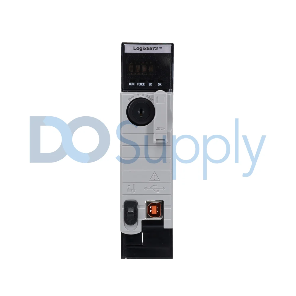
Quarterly cleaning of drive ventilation paths and fan inspection eliminates the majority of overtemperature faults before they cause production stoppages. Annual tightening of all power terminations, particularly at T1/T2/T3 and DC bus terminals, prevents resistance heating and intermittent overcurrent conditions that are difficult to trace reactively. PLC programs must be backed up to offline storage after every modification; on ControlLogix and CompactLogix systems, Compact Flash or SD cards provide non-volatile storage that eliminates battery dependency. SLC 500 and MicroLogix batteries require replacement every one to two years, regardless of low-battery warnings. Monthly review of drive fault queues and PLC fault logs catches recurring fault patterns before they escalate. We have a guide on maintaining PowerFlex 7 series drives here as well.
Final Thoughts
In conclusion, systematic Allen-Bradley troubleshooting, grounded in fault code interpretation, parameter-level analysis, and structured hardware isolation, separates a 15-minute recovery from a multi-hour outage. If your troubleshooting points to a failed drive, a fried IGBT, or a power supply that’s not holding up under load, we at DO Supply can help. We carry a wide range of Allen-Bradley PowerFlex drives, ControlLogix and CompactLogix modules, power supplies, and I/O cards. Need a replacement fast? We stock common part numbers and can ship quickly to minimize your downtime. We also offer professional repairs on Allen-Bradley drives and PLCs when a full replacement isn’t necessary, all backed by our two-year warranty. Browse our Allen-Bradley inventory or call us to get the right part for your application.
DO Supply Inc. makes no representations as to the completeness, validity, correctness, suitability, or accuracy of any information on this website and will not be liable for any delays, omissions, or errors in this information or any losses, injuries, or damages arising from its display or use. All the information on this website is provided on an "as-is" basis. It is the reader's responsibility to verify their own facts.