MicroLogix Maintenance Guide: Keeping Your Legacy Controllers Reliable
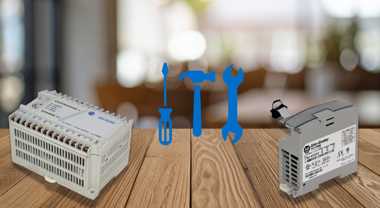
Over the past two decades, Allen-Bradley MicroLogix controllers have been the backbone of many industrial automation applications. In favor of Compact Logix and Micro800, Rockwell Automation has phased out the MicroLogix product line; however, a large worldwide installed base continues to rely on MicroLogix controllers for daily operations. MicroLogix controllers automate countless OEM (Original Equipment Manufacturer) panels, commercial HVAC (Heating, Ventilation, and Air Conditioning) equipment, packaging lines, agricultural machines, and municipal water systems.
The majority of MicroLogix installations are now over a decade old, with most of these controllers having been in continuous operation for 10 to 20 years. As such, to ensure operational continuity and reliability, their regular and effective maintenance is vital and no longer an option. Power fluctuations, component wear and degradation, harsh industrial environments, communication errors, and aging/obsolete electronics contribute to PLC failures when left unaddressed. With a proper knowledge of how MicroLogix hardware functions over time and with structured maintenance, the good news is that these legacy Allen-Bradley MicroLogix controllers can continue to perform optimally for many more years.
This article provides an engineering-focused, practical guide on Allen-Bradley MicroLogix maintenance, incorporating common troubleshooting techniques, field experience, and manufacturer recommendations. It is designed to assist engineers, maintenance teams, and technicians in planning for long-term support of Allen-Bradley MicroLogix systems and enhancing system uptime.
MicroLogix Series Overview
The MicroLogix family consists of five controller models: MicroLogix 1000, 1100, 1200, 1400, and 1500. Each MicroLogix controller model has a different programming capacity, I/O expansion capabilities, communication options, and technical specifications. With knowledge of the hardware features of each MicroLogix controller version, engineers/technicians can identify the most likely failure modes and maintenance requirements.
MicroLogix 1000
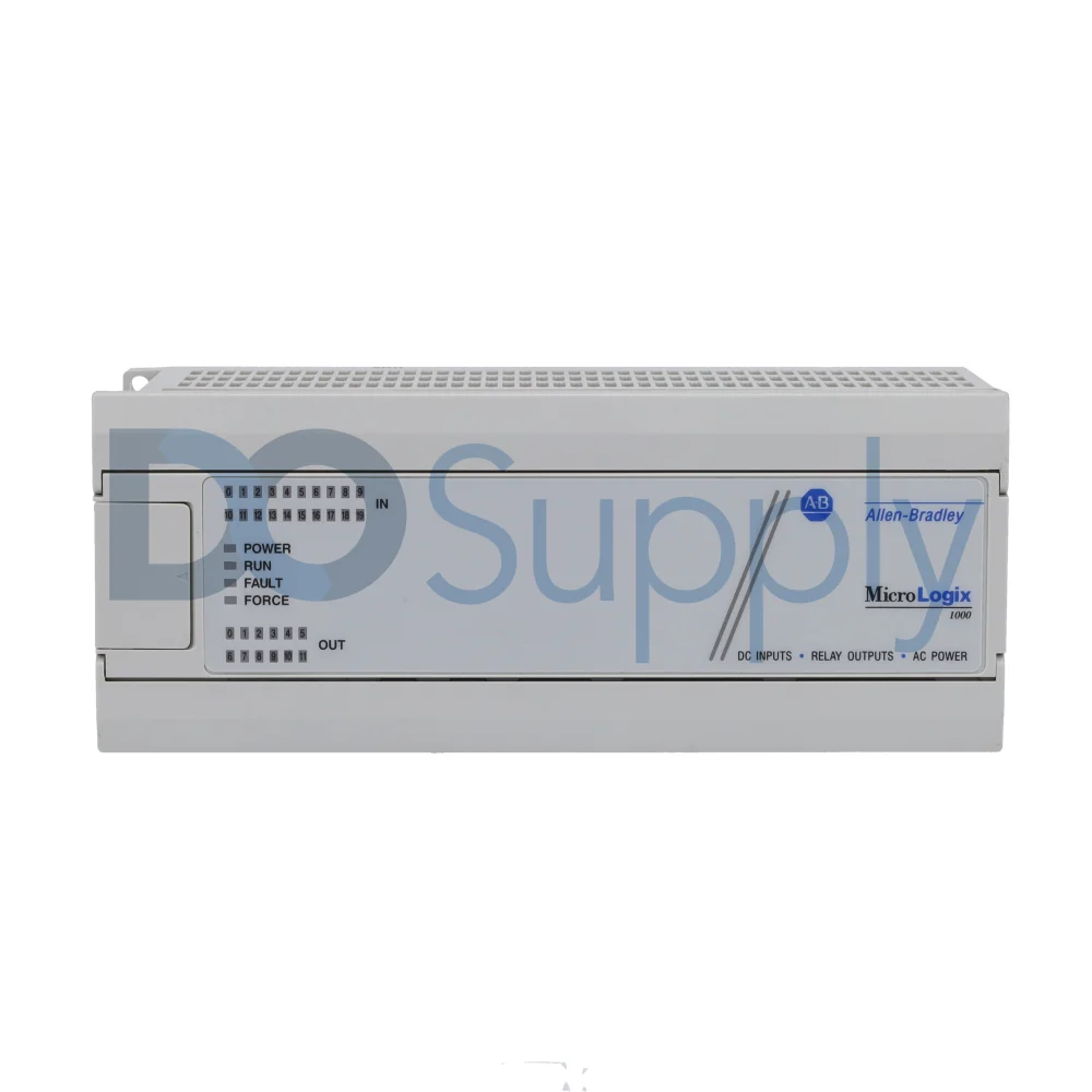
The MicroLogix 1000 is a high-speed micro-PLC with advanced networking capabilities. It is ideal for space-limited applications requiring up to 32 I/O points. While its compact design reduces the number of mechanical failure points, it also implies that if a single component malfunctions, the entire controller must be replaced. MicroLogix 1000 units can develop issues such as malfunctioning relay outputs, diminishing internal power supplies, and analog channel drift over many years of continuous operation.
Keeping it Working
- Inspect the controller’s output relays on an annual basis. Checking for stuck, chattering relays or contacts that heat up.
- Inspect input voltage levels periodically. Under typical load conditions at the terminals, monitor the DC input voltage.
- In harsh industrial environments, replace the entire MicroLogix 1000 controller unit proactively.
- Assess the performance of the power supply. Insufficient power supply is the primary cause of multiple issues in MicroLogix 1000 PLCs.
MicroLogix 1100
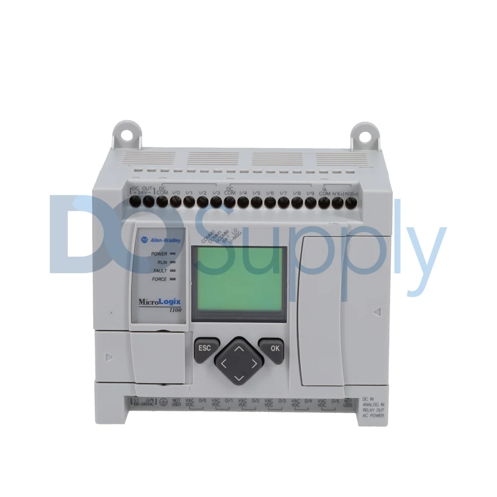
The MicroLogix 1100 controller offers a built-in LCD screen and keypad, Ethernet/IP connectivity via an Ethernet port, data logging, online editing functionality, embedded Web server, and an isolated RS-485/RS-232 combo serial port. It supports up 18 Input/Output points (2 analog inputs, 6 discrete outputs, and 10 digital inputs). Although the additional features enhance the controller’s usability and functionality, they also introduce more components that can deteriorate with age. The Ethernet port can experience interference or corrosion, the LCD backlight can wear out, and the keypad buttons may become unresponsive. However, MicroLogix 1100 units remain quite dependable with adequate maintenance.
How to Care for the MicroLogix 1100
- Avoid continuous use of the embedded LCD. Reduce brightness and configure the LCD’s backlight timeouts appropriately
- Safeguard the controller against power surges. Install Ethernet isolators or surge suppressors in the control system in extremely noisy environments
- Check the Ethernet connection regularly. Inspect the RJ-45 port for elasticity, worn gold contacts, or cracked latch tabs.
MicroLogix 1200
The MicroLogix 1200 features a processor, real-time clock, removable memory module, and a power supply unit. It is available in 24- and 40-point I/O configurations; the I/O count can be extended using rack-less I/O expansion modules. However, the additional I/O expansion modules come with mechanical joints and extra connectors that may gather oxidation or loosen over time.
Maintenance Recommendations
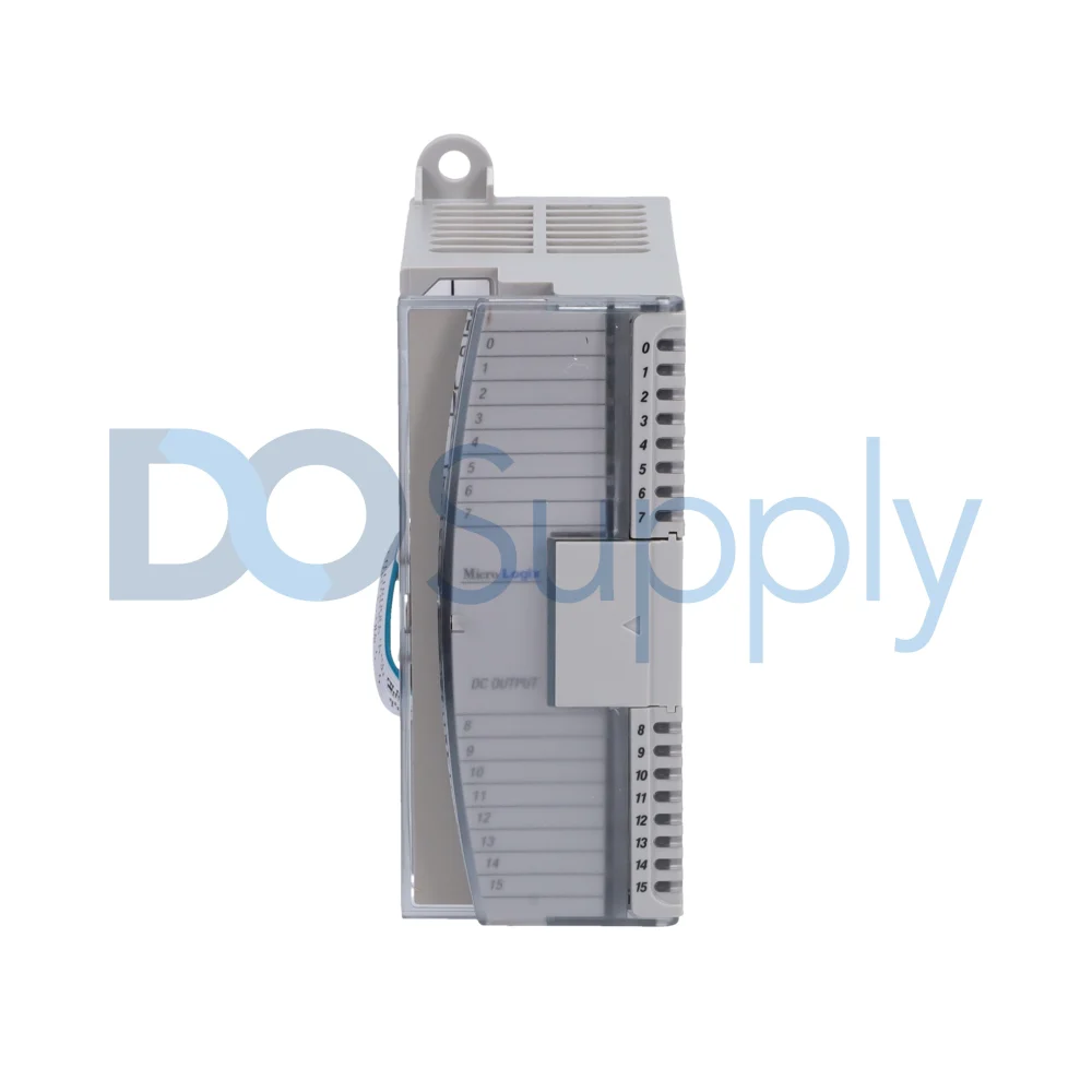
- The memory module requires regular reseating and cleansing to maintain consistent operation
- Integrate Electromagnetic Interference (EMI) protection and avoid setting up the High-Speed Counter connectors adjacent to motor power lines
- If necessary, apply an anti-corrosion grease to electrical connections and tighten any loose connections
- Recalibrate potentiometers if they’re frequently used. Pot settings are likely to shift by 5 to 10% over decades of vibration.
- Remove and reconfigure the I/O expansion modules as needed
- Replace the CPU battery periodically
MicroLogix 1400
The MicroLogix 1400 controller contains a processor, power supply, an Ethernet Port, input and output circuits, a non-isolated RS-232 serial communication port, and an isolated combination RS-485/RS-232 serial communication port. Each MicroLogix controller supports 6 analog I/O points (2 outputs and 4 analog outputs) and up to 32 discrete I/O points (12 discrete outputs and 20 digital inputs).
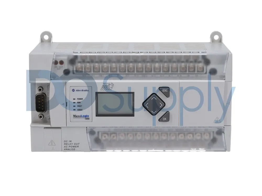
Essentially, the MicroLogix 1400 series is designed to extend application coverage through a faster high-speed counter, embedded analog inputs, Ethernet communication, and PTO (pulse train output) capabilities. As the most advanced MicroLogix controller model, the MicroLogix 1400 offers data logging, a built-in web server, an SD card slot, online editing, and improved Ethernet/IP support. While the added features and capabilities improve the controller’s functionality, they also make it vulnerable to issues such as Ethernet noise, SD card wear, and potential log file corruption if proper maintenance is not carried out.
Inspection and Maintenance Points
- The processor’s battery requires periodic replacement, every two to three years. To avoid data loss, replace the battery while the MicroLogix 1400 controller is still powered on
- Access the accuracy of the built-in real-time clock (RTC) regularly
- Verify the calibration of the analog channels to avoid vibration issues
- Due to the MicroLogix 1400 sensitivity to ground loops, add panel shielded and grounding communications. This improves the durability of the high-speed counter (HSC) and pulse-width modulation (PWM) output
- Ensure that the MicroLogix 1400 controller is installed in a suitable industrial enclosure to reduce the effects of environmental exposure and electrical interference (e.g., Overvoltage Category II)
MicroLogix 1500
The MicroLogix 1500 PLC has a modular design, featuring a removable processor, memory module, communication cables, power cables, and embedded I/O modules. The CPU connects to a separate base unit that also contains input and output circuits and a power supply. This MicroLogix controller is available with 28 or 24 built-in I/O points. Additional I/O points can be added using the Allen-Bradley Compact I/O modules. While the MicroLogix 1500 modular design offers great application versatility, its ribbon cables (used to connect the expansion I/O modules) and base connectors may experience contact issues due to years of mechanical stress and dust. This can be a source of potential issues related to power limitations, signal integrity, and physical durability. These cables encounter contact issues due to physical damage, corrosion, loose connections, or interference.
How to Care for the MicroLogix 1500
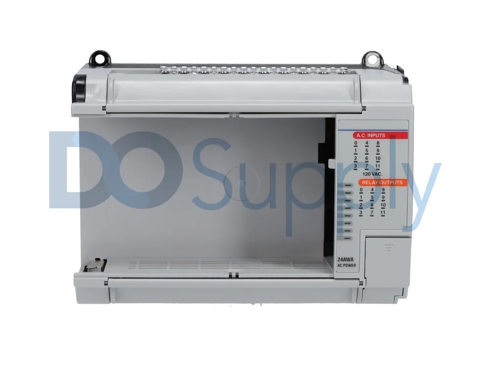
- On an annual basis, clean and reset the MicroLogix 1500 memory module
- Perform electrical contact maintenance. When cleaning connectors, apply gentle pressure to avoid damaging them. Also, be sure to use the recommended electrical contact cleaner and a lint-free cloth or cotton swab.
- Assess for fragility in the ribbon cables. If connections are poor or loose, carefully reseat the ribbon cables. If damaged, replace or repair the damaged sections.
- Verify the calibration of the analog PLC inputs regularly
- Replace the controller’s permanent battery every 7 or 8 years, or sooner if your system experiences technical issues. A new battery will help retain the memory if the MicroLogix 1500 processor fails.
- Be sure to install a backup battery whenever the processor’s Battery Low indicator turns on.
Preventive Maintenance Strategy
To extend the operational life of MicroLogix controllers, especially as they enter the late stages of their life span, requires a robust preventive maintenance policy. In comparison with newer PLCs with sophisticated diagnostics, MicroLogix systems rely on human assessment, instrument-based testing, and external observation. Regular preventive maintenance must therefore address communication health, mechanical condition, environmental stability, electrical integrity, and program reliability through regular, organized inspection routines.
Regular evaluation of environmental conditions helps facilities by guaranteeing that the controller’s enclosure maintains adequate ventilation, acceptable temperature levels, protection from moisture, dust, vibration, and other contaminants.
Quarterly electrical inspections help confirm that grounding systems are secure, power supplies are operating within the correct limits, and wiring is free from damage and wear. Semiannual configuration reviews and program backups help maintain data integrity, prevent memory corruption, unintentional changes, and battery failure, which could lead to the accidental loss of program logic.
Preventive maintenance works best when technicians have an anticipatory approach. MicroLogix controllers do not fail suddenly; they exhibit small, mild symptoms that worsen gradually. Through systematic inspections, these early signs can be recognized, thus providing useful lead time for replacement or repairs and reducing unnecessary downtime.
Communication Port Maintenance
Communication reliability is crucial for MicroLogix systems linked to SCADA systems, HMIs, or networks. Depending on the model, MicroLogix controllers use RS-485, RS-232, and Ethernet ports. Over time, due to cable strain, mechanical wear, and contact oxidation, the Ethernet ports degrade. Accumulation of dust inside the connectors causes interference with signal transmission. Particularly in environments with a lot of movement or vibration, Ethernet cables become damaged and brittle.
Serial communication has challenges. Worn screws, bent pins inside DB9 connectors, or frayed RS-232/RS-485 cables can cause sporadic failures that are difficult to replicate. Examining cable integrity, ensuring that cables are securely mounted, and confirming the appropriate termination of resistors are all vital measures of preventive maintenance.
Electrical Maintenance
The main aim of electrical maintenance in MicroLogix controllers is to ensure noise-free, stable, and clean power so that the controller can function dependably as it ages. The most crucial task is to check the power supply’s health, because aging regulators and capacitors can introduce ripple and voltage drops that cause CPU resets and faults. In addition to inspecting noise, heat, or discoloration issues that indicate internal deterioration, technicians should check the voltage under the actual machine load and at idle. Corroded or lost ground points may cause electrical noise that affects communication stability and analog accuracy; therefore, grounding quality is a crucial factor. Verifying shield continuity, cleaning ground lugs, and removing accidental ground loops are examples of preventive work.
Physical Inspection
It is important to visually and regularly inspect the electrical terminals and wiring of your MicroLogix control system. Terminals loosen due to age, vibration, and thermal expansion, resulting in resistive heating. Replacement of brittle conductors, torque checking, and termination of oxidized wires must be performed by a technician. Equally important is noise management, removing damaged shielding, separating signal cables from high-power cords, and eliminating damaged shielding. This safeguards the controller from electrical disturbances. A combination of grounding integrity, wire servicing, and noise-reduction techniques may considerably extend the lifespan and durability of MicroLogix controllers in manufacturing operations.
I/O Module Maintenance
Fostering the electrical connection between the controller and the physical machine is the primary objective of I/O module repair on a MicroLogix system. The theoretical framework is that every solenoid, sensor, valve, actuator, and motor sensor is contingent on the I/O Modules for distinct signal transfer. Vibration, electrical load, and heat cause physical stress to these modules over time. The most crucial maintenance tasks involve inspecting the interaction between the electrical hardware and the mechanical world.
Inspection of terminal integrity is an immensely significant task. Gearbox or motor vibration gradually loosens the connection screws, which creates poor output signals and intermittent readings. To ensure low resistance and firm connections, torque monitoring is performed across every I/O terminal. Inspection of wires for pulled conductors, cracked insulation, or frayed shielding must be done mostly where cables extend or transverse adjacent to moving equipment.
Environmental and physical inspection
Physical and environmental examination ensures that MicroLogix controllers are shielded from vibration, dust, moisture, and heat, four variables that gradually degrade hardware. Technicians must frequently monitor cabin temperatures and improve airflow or ventilation when hotspots occur, since excess heat diminishes the solder intersections. Vibration of mechanical equipment and motors gradually stresses the DIN rail, loosens terminals, and compromises the terminals. Accumulation of dust traps heat, when mixed with oil or humidity, can be conductive.
A focus on the four environmental parameters prevents most long-term failures, significantly improving the lifespan and reliability of MicroLogix systems in industrial manufacturing settings. Inspection should involve examining for water streaks, rust, swollen insulation, and technicians must ensure enclosure heaters, proper sealing, or gaskets. Fixing mounting and re-torquing wires are vital.
Battery management
Every 2-3 years, the MicroLogix CPU battery should be replaced in accordance with the manufacturer’s instructions. This prevents unanticipated failures since worn batteries frequently decline in capacity. Keep the PLC switched on during replacement to prevent instantaneous program loss. During routine maintenance, plan replacements to eliminate the risk of power interruption.
The controller’s data files, data settings, and complete software are lost if the PLC loses power and the battery is dead. Recovery is impossible or difficult in many vintage systems that might lack backup. MicroLogix batteries are lithium-based and contain hazardous materials that must be disposed of through hazardous waste management, not standard garbage. Spares should be kept at room temperature to prevent degradation before use.
Data integrity and program maintenance
The validity of stored logic for MicroLogix controllers should be ensured through data integrity and program maintenance. Regular evaluation of the ladder program to remove obsolete temporary fixes, redundant rungs, or packed data files marks the initial phase of proper maintenance. Since MicroLogix RAM is battery-powered, periodic backups are essential. The controller can swiftly erase its operating system if power is switched off while the battery is depleted. Maintaining several scheduled backups, both electronic and on-site, ensures rapid recovery in the event of a system malfunction.
To prevent data deterioration or corruption, SD cards and memory modules, especially in humid or dusty environments, should also be inspected and disinfected. Since defects or exceptions could alter essential parameters and calibrated values, technicians must ensure these remain valid in their databases. When integrated as a whole, these procedures protect the logic, eliminate unforeseen failures, and ensure that the MicroLogix system’s function always resumes and operates properly.
Troubleshooting Basic MicroLogix Failures
| Failure Modes | Possible Causes | Corrective Measures |
| Intermittent CPU Failures | Unstable power or electrical buzz | Improve grounding, regulate power, and replace batteries |
| Ethernet dropouts | Noise, damaged cables, and rusty connectors | Improve shielding, replace the cable, or clean the ports |
| Variability in analog values | Thermal stress, grounding challenges, and analogue drift | Fix the grounding, remove or readjust the module |
| Sensor input inaccuracy | Weak terminals or worn-out wires | Use interposing relays and fasten the terminals |
| Not switching between outputs. | Excessive workload, circuit degradation | Use interposing circuits or replace the module |
| Failure in PLC powering | Aging of the internal regulator, power supply fault | Gauge output, switch off the supply chain, and check ripple |
Final Thoughts
The MicroLogix series of PLCs is robust and can withstand the test of time. However, like any piece of equipment, it will need to be maintained to keep it performing at its best. We hope this guide was helpful in keeping your PLCs running as smoothly as the day you got them, but if your PLCs still need more attention, we offer repair services here to fix or replace malfunctioning equipment. We also have replacement parts, optional modules, and even newer PLCs available for upgrade. Though if you are looking for reasons to keep and repair your MicroLogix line, then we have an article here going over why it might be a good idea.There are many ways to go about this, which is why we encourage you to stop by our site to see our options, or call us to schedule a repair for your existing equipment. As always, thank you for reading.
DO Supply Inc. makes no representations as to the completeness, validity, correctness, suitability, or accuracy of any information on this website and will not be liable for any delays, omissions, or errors in this information or any losses, injuries, or damages arising from its display or use. All the information on this website is provided on an "as-is" basis. It is the reader's responsibility to verify their own facts.